Preparation method of rigid carrier substrate and flexible oled display panel

A technology for carrying substrates and display panels, applied in the field of OLED display panels, can solve problems affecting the quality of flexible OLED display panels, temperature rise of flexible OLED display panels, and easy friction, etc., to prevent performance from being affected, reduce deformation, reduce heat effect

Active Publication Date: 2021-03-02
TCL CHINA STAR OPTOELECTRONICS TECH CO LTD
View PDF8 Cites 0 Cited by
  • Summary
  • Abstract
  • Description
  • Claims
  • Application Information

AI Technical Summary

Problems solved by technology

[0003] Wherein, the commonly used method for separating the adhesive layer from the carrier substrate is mainly the peeling method, but since the material of the adhesive layer is often a high polymer material such as parylene, the flexible OLED display panel And when the adhesive layer is peeled from the carrier substrate, the adhesive force generated by the adhesive layer on the carrier substrate is relatively large, and the pulling force of the peeling usually acts on the central area away from the object to be peeled off, so that the flexible OLED display The flexible substrate of the panel is easily deformed under the tension of adhesion and peeling, and when peeling, friction between the adhesive layer and the carrier substrate is likely to occur, and the heat generated will make the flexible OLED The temperature of the display panel increases, which in turn affects the quality of the fabricated flexible OLED display panel

Method used


Image

  • Preparation method of rigid carrier substrate and flexible oled display panel
  • Preparation method of rigid carrier substrate and flexible oled display panel
  • Preparation method of rigid carrier substrate and flexible oled display panel

Examples


Embodiment Construction

[0021] In order to make the object, technical solution and advantages of the present invention clearer, the specific implementation manners of the present invention will be described in detail below in conjunction with the accompanying drawings. Examples of these preferred embodiments are illustrated in the accompanying drawings. The embodiments of the invention shown in and described with reference to the drawings are merely exemplary, and the invention is not limited to these embodiments.

[0022] Here, it should also be noted that, in order to avoid obscuring the present invention due to unnecessary details, only the structures and / or processing steps that are closely related to the solution according to the present invention are shown in the drawings, and the relationship between them is omitted. Little other details.

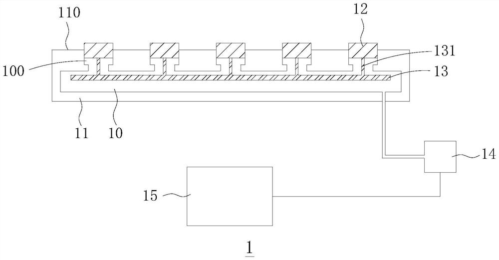
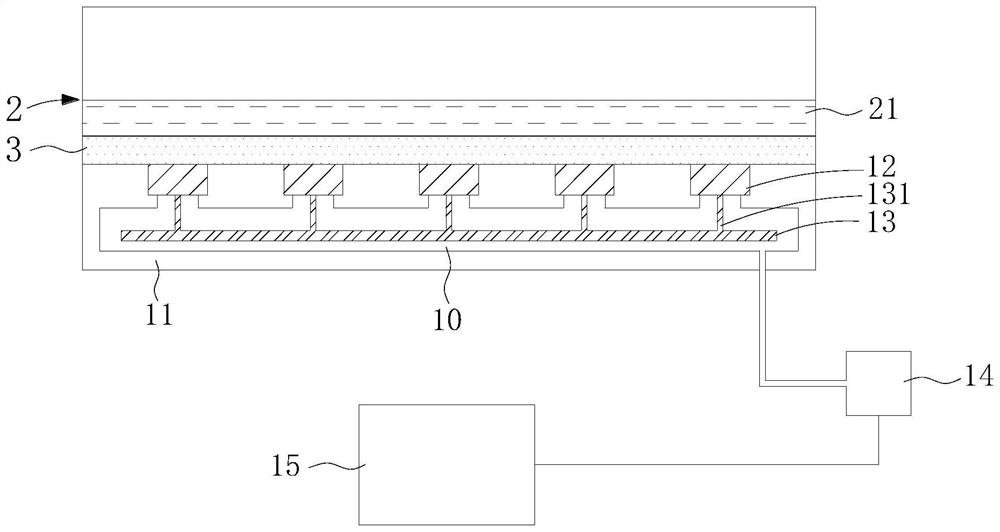
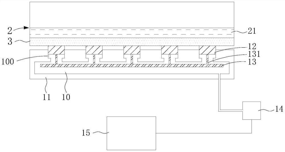
[0023] refer to figure 1 As shown, this embodiment provides a rigid carrier substrate 1 for carrying the flexible OLED display panel 2 during the manufac...


PUM


Abstract

The invention discloses a method for preparing a rigid bearing substrate and a flexible OLED display panel. A movable supporting member is arranged in the substrate body of the rigid bearing substrate, and the supporting member is used to press the flexible OLED display panel. The flexible OLED display panel can be quickly separated from the rigid carrier substrate adhered by the adhesive layer under relatively concentrated force. Compared with the solution of directly peeling the flexible OLED display panel with the adhesive layer from the rigid carrier substrate in the prior art, the present invention can reduce the force of adhesion and peeling of the flexible substrate during the separation process. Under the condition of deformation, reduce the heat generated by the friction between the adhesive layer and the rigid bearing substrate, prevent the optical characteristics and other properties of the flexible OLED display from being affected, and improve the yield rate.

Description

technical field [0001] The invention relates to the technical field of OLED display panels, in particular to a method for preparing a rigid bearing substrate and a flexible OLED display panel. Background technique [0002] In the prior art, flexible OLED display panels are usually prepared by the following scheme: provide a rigid carrier substrate, such as glass or steel plate, prepare an adhesive layer on the carrier substrate, and then deposit or attach the adhesive layer on the adhesive layer. The flexible substrate of the flexible OLED display panel, so that the flexible substrate is fixed on the carrier substrate through the adhesive layer, so as to continue to prepare the remaining devices of the flexible OLED display panel on the flexible substrate: TFT array layer and an OLED display unit, and finally separate the carrier substrate from the adhesive layer and the flexible OLED display panel on it, remove the adhesive layer on the flexible OLED display panel, and obta...

Claims


Application Information

Patent Timeline
Patent Type & Authority Patents(China)
IPC IPC(8): H01L27/32H01L51/56G09F9/30
CPCG09F9/301H10K59/00H10K71/80
Inventor 徐向阳
Owner TCL CHINA STAR OPTOELECTRONICS TECH CO LTD
Why Eureka
Try Eureka