Improved structure of light emitting sub-module

A light emission sub-module and improved structure technology, applied in the direction of light guides, optics, optical components, etc., can solve problems such as the influence of optical characteristics

Inactive Publication Date: 2020-09-01
ELEOCOM INC
View PDF8 Cites 0 Cited by
  • Summary
  • Abstract
  • Description
  • Claims
  • Application Information

AI Technical Summary

Problems solved by technology

The optical characteristics of the light output by the light output port 957 of the output port 952 of the optical engineer 95 will be affected by the temperature change of the outside world

Method used


Image

  • Improved structure of light emitting sub-module
  • Improved structure of light emitting sub-module
  • Improved structure of light emitting sub-module

Examples


Embodiment Construction

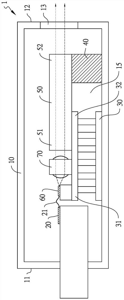
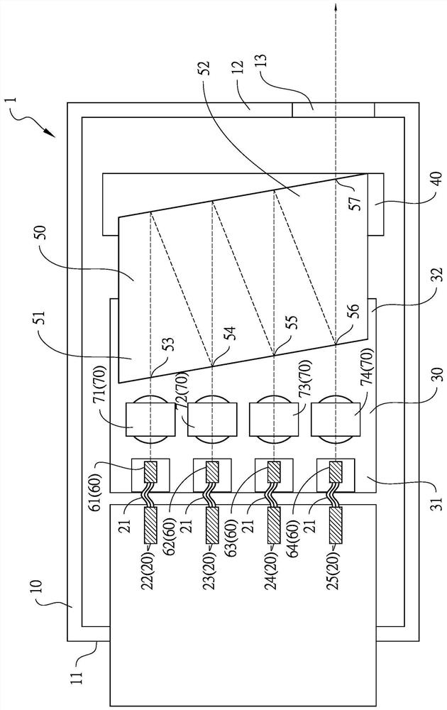
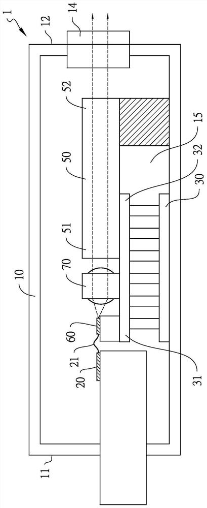
[0035] see Figure 1A , which is a schematic cross-sectional view of a specific embodiment of an improved structure of a light emitting sub-module of the present invention. Please also see Figure 1B , which is Figure 1A A schematic top view of an embodiment. The improved structure 1 of a light emitting sub-module of the present invention includes: a packaging box 10, a laser diode driver group 20, a flexible circuit board 21, an electrothermal cooling chip 30 (TEC: thermoelectric cooler), an optical engineer The support column 40 , an optical multiplexer 50 , a laser diode group 60 , and a collimator lens group 70 . Wherein the packaging box 10 is made of metal. The packaging box 10 has a circuit control terminal 11 and a light emitting terminal 12 . The light emitting end 12 has a light emitting hole 13 . The laser diode driver group 20 is disposed on the circuit control terminal 11 . The laser diode driver group 20 includes four laser diode drivers 22 , 23 , 24 , 25...


PUM


Abstract

An improved structure of a light emitting sub-module comprises a packaging box, a laser diode driver group, an electric heating and cooling chip, an optical device, an optical device supporting column, a laser diode group and a collimating lens group. The packaging box body is provided with a circuit control end and a light emitting end, and the light emitting end is provided with a light emittinghole. The laser diode driver group is arranged on the circuit control end; the electric heating and cooling chip and the optical device supporting column are respectively arranged in the packaging box, the electric heating and cooling chip is arranged between the laser diode driver group and the optical device supporting column, and the optical device supporting column is arranged between the electric heating and cooling chip and the light emitting end. The optical device is provided with an input end and an output end, the input end of the optical device is arranged at one end of the electric heating and cooling chip, and the output end of the optical device is arranged on the optical device supporting column. The laser diode group is arranged at the other end of the electric heating andcooling chip, and the laser diode group is electrically connected with the laser diode driver group.

Description

technical field [0001] The invention relates to an improved structure of a light-emitting sub-module, in particular to an improved structure of a light-emitting sub-module with an electrothermal cooling chip. Background technique [0002] see Figure 10A , which is a specific embodiment of a light emitting sub-module in the prior art. Please also see Figure 10B , which is Figure 10A A schematic top view of an embodiment. A light emitting sub-module 9 of the prior art includes: a packaging box 90, a laser diode driver group 92, a flexible circuit board 921, an electrothermal cooling chip 93 (TEC: thermoelectric cooler) and an optical worker 95 (optical multiplexer), a laser diode group 96, an optical window lens 904, a fiber coupling part 98 and a collimating lens group 97. The packaging box 90 has a circuit control terminal 901 and a light emitting terminal 902 . The light emitting end 902 has a light emitting hole 903 . The laser diode driver group 92 includes four l...

Claims


Application Information

Patent Timeline
Patent Type & Authority Applications(China)
IPC IPC(8): G02B6/42
CPCG02B6/4204G02B6/4208G02B6/4271G02B6/4281G02B6/4287G02B6/4296
Inventor 内田俊一
Owner ELEOCOM INC
Why Eureka
Try Eureka