
Efficient split type infrared burner of infrared stove

An infrared burner and split-type technology, which is applied in the field of household gas cookers, can solve the problems of complex processing technology, many processing steps, and high maintenance complexity, and achieve the effects of simple processing steps, beautiful structure and appearance, and solving antifouling defects

Pending Publication Date: 2022-12-02
GUANGZHOU REDSUN GAS APPLIANCE
View PDF5 Cites 0 Cited by
  • Summary
  • Abstract
  • Description
  • Claims
  • Application Information

AI Technical Summary

Problems solved by technology

[0003] 1. The infrared burner adopts an integral structure design. The ejector naturally injects air into the burner cavity through the gas pressure. Since the mixing cavity is a columnar structure, there is no design of a shunt structure, which is prone to local uneven combustion and local high temperature , increasing the chance of nitrogen oxide formation
[0004] 2. The infrared burner adopts an integral structure design. The ejector naturally ejects air into the burner cavity through the gas pressure. Since the mixing chamber is a columnar structure, there is no design of a shunt structure, and the gas and air are in the ejector and the furnace chamber. The internal mixing time is short, the gas and air are not fully premixed, and a part of the gas layer fluid is formed in the furnace cavity, which is likely to cause defects such as incomplete combustion and low thermal efficiency
[0005] 3. The infrared burner adopts an integral structure design. The ejector naturally ejects air into the burner cavity through the gas pressure. Due to the unreasonable design of the porous combustion radiation plate structure, the resistance of the head is large, which reduces the primary air of the ejector. Therefore, the gas-air mixture cannot achieve complete combustion once it reaches the combustion zone, and secondary air is needed to achieve complete combustion, and then the flame is elongated and the thermal efficiency decreases. Strictly speaking, the combustion method of this type of product is closer to the atmosphere Stove
[0006] 4. In the infrared burner with integral structure design, there are still many porous combustion radiant plates and burner heads that are designed by adhesive bonding and sealing. If the porous combustion radiant plate is accidentally damaged and needs to be replaced, it needs to be disassembled Panels, burners and other parts can only be replaced, resulting in high maintenance complexity and low maintenance efficiency
[0007] 5. The infrared burner with integral structure design cannot form a completely closed structure between the infrared burner and the panel (or liquid receiving plate), so during the cooking process, it is very easy to cause stains to flow into the stove from the gap between the two inside, and then flow into the interior of the cabinet, affecting the user experience
[0008] 6. The infrared burner adopts a split structure design. The premixing chamber is basically designed with a cast iron structure. The inner wall of the injection tube has a low finish, which affects the ability of one injection, resulting in the gas-air cannot be completely premixed, and the flame is elongated. Decreased thermal efficiency
[0009] 7. The infrared burner adopts a split structure design, and the premixing chamber directly adopts an atmospheric furnace chamber structure. The parameters of the ejector tube and the chamber cannot meet the design requirements, resulting in the inability to achieve complete premixing of gas-air, and the flame is elongated. Decreased thermal efficiency
[0011] 9. For the mainstream infrared burners currently on the market, the ignition needle and ion needle are generally placed in the center hole of the furnace head, and they are all connected by screws. If the porous combustion radiation plate is accidentally damaged and needs to be replaced, the screws need to be removed and loosened Ignition needle and ion needle, if the screws are corroded, it will cause high maintenance complexity and low maintenance efficiency
[0012] 10. The mainstream infrared burners currently on the market are stamping burners and die-casting burners. Due to the limitations of stamping and die-casting processes, most of the ejector tubes and furnace chambers are welded or screw-fixed. , resulting in many processing steps, complicated processing technology and high processing cost

Method used


Image

  • Efficient split type infrared burner of infrared stove
  • Efficient split type infrared burner of infrared stove
  • Efficient split type infrared burner of infrared stove

Examples


Embodiment 1

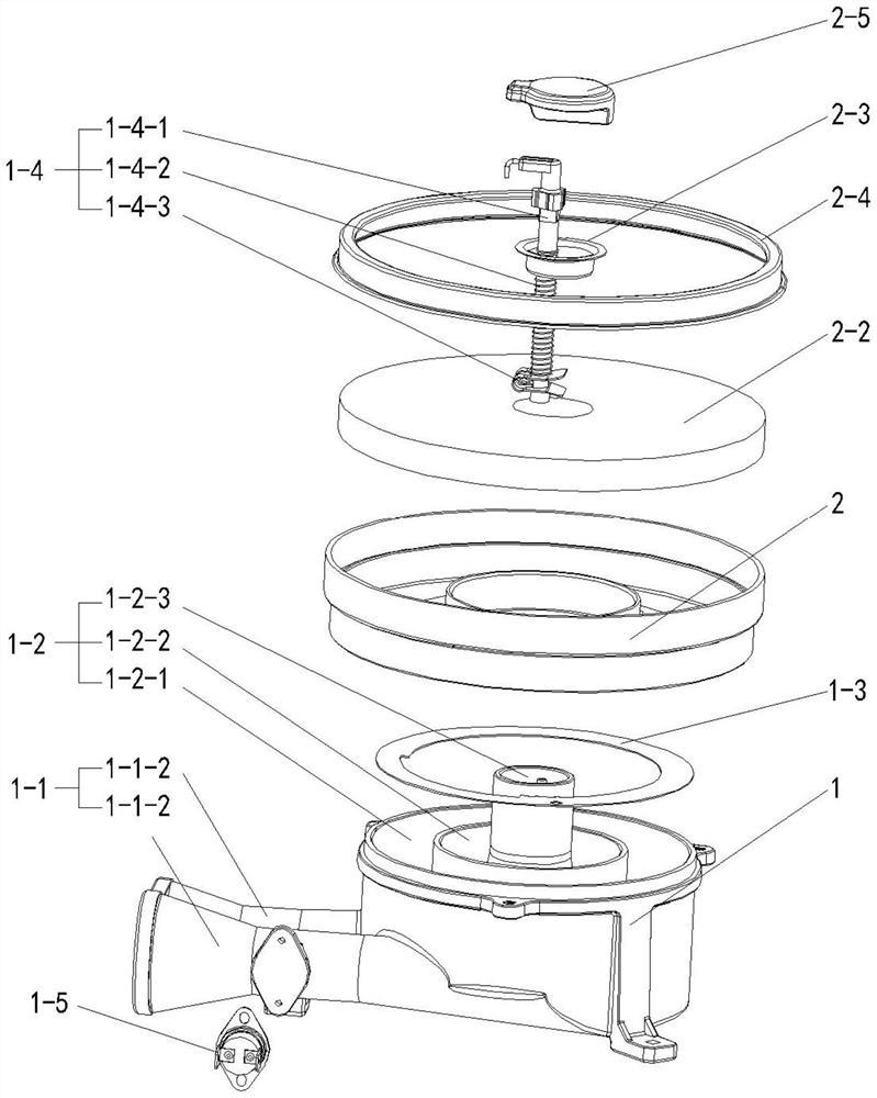
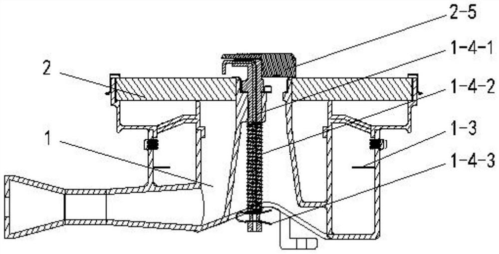
[0074] like Figure 1 to Figure 8 , this embodiment provides a high-efficiency split-type infrared burner for an infrared stove, including:

[0075] The premixing part 1 and the combustion part 2, the premixing part 1 and the combustion part 2 are matched and connected,

[0076] The ejector 1-1, the first mixing chamber 1-2, the splitter plate 1-3 and the ignition probe assembly 1-4 are arranged in the premixing part 1; wherein the ejector 1-1 includes the inner ejector 1- 1-1 and outer ejector 1-1-2;

[0077] The first mixing chamber 1-2 includes the middle part of the first mixing chamber 1-2 arranged from the inside out, the first inner mixing chamber 1-2-2 and the first outer mixing chamber 1-2-1, the first mixing chamber 1 -2 The middle part is cylindrical, the first inner mixing chamber 1-2-2 and the first outer mixing chamber 1-2-1 are annular, the middle part of the first mixing chamber 1-2, the first inner mixing chamber 1-2 -2 and the first outer mixing chamber 1-...

Embodiment 2

[0092] like Figure 9 , the high-efficiency split-type infrared burner of an infrared cooker provided in this embodiment is different from Embodiment 1 in that the diverter plate 1-3 is divided into the inner diverter plate 1-3A and the outer diverter plate 1-3B, which are combined with the premixed Part 1 has an integrated structure. Specifically, the inner splitter plate 1-3A is arranged in the first inner mixing chamber 1-2-2, and the outer splitter plate 1-3B is arranged in the first outer mixing chamber 1-2-1. The structure is more Concentration, simple processing technology.

Embodiment 3

[0094] like Figure 10The difference between the high-efficiency split-type infrared burner for an infrared stove provided in this embodiment and the embodiment 1 is that the combustion part 2 is provided with a guide structure inclined upward from the inside to the outside, which can effectively guide the mixed gas evenly. The flow is distributed to each fire hole of the porous combustion radiant plate 2-2, which has the advantages of uniform combustion and reduced local high temperature.


PUM


Abstract

The invention belongs to the technical field of household gas cookers, and provides an efficient split type infrared burner of an infrared stove, the efficient split type infrared burner of the infrared stove comprises a premixing part and a burning part, the premixing part is connected with the burning part in a matched mode, and the premixing part is provided with an ejector, a first mixing cavity, a splitter plate and an ignition probe assembly; the combustion part is provided with a second mixing cavity, a porous combustion radiant panel and an antifouling cover; one end of the ejector is connected with the first mixing cavity, the splitter plate is arranged in the first mixing cavity, and the ignition probe assembly penetrates through the first mixing cavity; the porous combustion radiant panel is matched with a cavity opening of the second mixing cavity, and the ignition probe assembly penetrates through the second mixing cavity and the porous combustion radiant panel. The combustor is provided with the two cavities, the premixing part adopts an integrated molding casting process, the processing procedure is simple, the splitter plate is arranged in the premixing part, the problems of primary air injection, complete premixing of gas and air and heat intensity consistency are fundamentally solved, and the combustor has the advantages of being low-carbon, environmentally friendly, efficient, energy-saving, safe, reliable and uniform in heating.

Description

technical field [0001] The invention belongs to the technical field of household gas stoves, and in particular relates to a high-efficiency split-type infrared burner for an infrared stove. Background technique [0002] For a long time, infrared stoves have become a model for many brands in the industry to compete and catch up because of their superiority in performance indicators such as high efficiency and energy saving, low-carbon environmental protection, cleanliness, uniform heating, and strong wind resistance, and have also become a model for many users. The first choice to buy. Infrared stoves are the product of infrared burners applied to civilian stoves. The infrared burner is designed with a completely premixed combustion method. When the burner is working, the combustible mixture is burned between the inner net and the outer net of the porous combustion radiation plate, and the burning surface temperature is as high as 1100 °C. The working principle of the commo...

Claims


Application Information

Patent Timeline
Patent Type & Authority Applications(China)
IPC IPC(8): F23D14/04F23D14/14F23D14/58F23D14/62F24C3/08F24C3/10F24C3/12
CPCF23D14/04F23D14/58F23D14/62F23D14/147F24C3/085F24C3/103F24C3/126
Inventor 不公告发明人
Owner GUANGZHOU REDSUN GAS APPLIANCE
Learn More