


Quick Research
Generate reliable direction feasibility study reports for your R&D in just a few steps.

Technical Q&A
Discover and master advanced knowledge NOW. Basics, ideas, possibilities, all at once.

Find Solutions
As an expert in R&D theories, this can generate solutions to your technical problems instantly.

Evaluate Feasibility
Analyze your overall solution with one click, know your potential R&D risks in advance.

Monitor Landscape
Get weekly tech updates, stay abreast of the latest tech innovations and key insights.
Rapid drying device for medical equipment
A technology for rapid drying and medical equipment, applied in drying, drying machines, heating devices, etc., can solve the problems of inconvenient identification of different medical equipment, inconvenient water vapor discharge, etc., and achieve the effect of speeding up work efficiency
- Summary
- Abstract
- Description
- Claims
- Application Information
AI Technical Summary
Problems solved by technology
Method used
Image

Examples
Embodiment 1
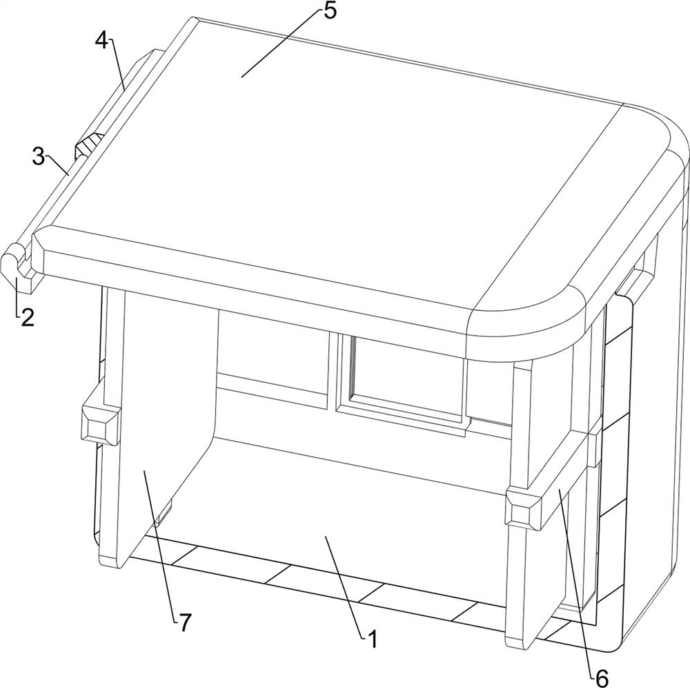
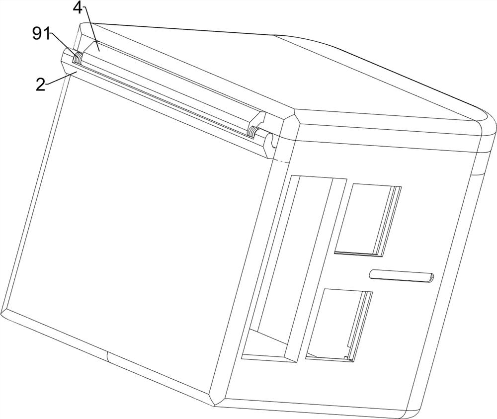
[0031] A rapid drying device for medical equipment, such as Figure 1-10 As shown, it includes a first casing 1, a fixing frame 2, a first rotating shaft 3, a connecting block 4, a first cover 5, a supporting frame 6, a heating plate 7, a rotating assembly 8 and a clamping assembly 9. The first casing 1 is on the left side. A fixing frame 2 is arranged on the upper part of the side wall, a first rotating shaft 3 is rotatably arranged on the fixing frame 2, a connecting block 4 is welded in the middle of the first rotating shaft 3, and a first cover 5 is welded on the right side wall of the connecting block 4, and the first cover 5 Located at the top of the first shell 1, the middle of the inner side wall of the first shell 1 is symmetrically welded with support frames 6 on the left and right sides, and the two support frames 6 are clamped on one side close to each other with a heating plate 7, and the fixed frame 2 is provided with a rotating assembly 8. The inner side of the ...
Embodiment 2
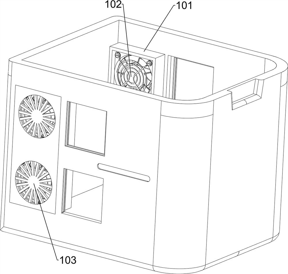
[0036] On the basis of Example 1, as figure 1 and Image 6 As shown, it also includes a heating assembly 10. The heating assembly 10 includes a second casing 101, a fan 102 and a second stopper 103. The first casing 1 has square grooves on the left side of the front and rear side walls. The second casings 101 are clamped together. Fans 102 are arranged symmetrically in both of the two second casings 101. A second block 103 is arranged symmetrically on one side of the two second casings 101 away from each other.
[0037] The staff starts the fan 102, and the four fans 102 rotate, so that the wind from the outside of the first casing 1 is drawn into the inside of the first casing 1, and the two heating plates 7 make the air drawn by the fans 102 into hot air, so that the first The hot air is transported in the first casing 1, which can achieve the purpose of removing the humid air, and then circulate the air inside the first casing 1. The two second blocks 103 prevent the four ...
Embodiment 3
[0039] On the basis of Example 2, as figure 1 , Figure 7 and Figure 10 As shown, it also includes a diffuser assembly 11. The diffuser assembly 11 includes a heat dissipation plate 111, a baffle 112 and a handle 113. The middle of the front and rear side walls of the first housing 1 is symmetrically opened with a square hole up and down. There are two radiating plates 111 connected between them. There are sliding grooves on the right side of the front and rear side walls of the first casing 1, and baffles 112 are slidably arranged in the two sliding grooves. In the guide groove, the two baffles 112 are on one side away from each other, and the middle part of the right side is welded with a handle 113, and the two handles 113 are respectively connected with the two guide grooves in a sliding manner.
[0040] like Figure 10 As shown, it also includes a push assembly 13, the push assembly 13 includes a cam 131, a third stopper 132, a push rod 133, a slider 134 and a third l...
PUM
 Abstract
Description
Claims
Application Information
 - R&D Engineer
- R&D Manager
- IP Professional
- Industry Leading Data Capabilities
- Powerful AI technology
- Patent DNA Extraction
Browse by: Latest US Patents, China's latest patents, Technical Efficacy Thesaurus, Application Domain, Technology Topic, Popular Technical Reports.
© 2024 PatSnap. All rights reserved.Legal|Privacy policy|Modern Slavery Act Transparency Statement|Sitemap|About US| Contact US: help@patsnap.com