
Preparation method of laser additive manufacturing hot crack sensitive material based on infrared auxiliary preheating

A laser additive and infrared technology, applied in the directions of additive manufacturing, additive processing, process efficiency improvement, etc., can solve the problems of reducing the mechanical properties of formed parts, uneven temperature distribution of the molten pool, material deformation and cracking, etc., to save equipment. The effect of retrofit cost, simple installation, and improved design freedom

Pending Publication Date: 2022-08-09
NANJING UNIV OF AERONAUTICS & ASTRONAUTICS
View PDF5 Cites 0 Cited by
  • Summary
  • Abstract
  • Description
  • Claims
  • Application Information

AI Technical Summary

Problems solved by technology

[0003] Due to the rapid cooling and solidification during the laser forming process, the solidification rate reaches 10 5 K / s, it is easy to cause high thermal stress inside the formed part, and these thermal stresses accumulate to form stress concentration, resulting in deformation and cracking of the material. For aluminum-based alloys (Al-Cu, Al-Li, Al-Zn, etc.), tungsten Due to the large temperature gradient and cyclic heating inside the molten pool during the laser rapid melting and solidification process, it is inevitable that the temperature distribution in the molten pool will be uneven. In this case, it is easy to generate thermal stress concentration, resulting in the formation of thermal cracks in the formed part, thereby reducing the mechanical properties of the formed part

Method used

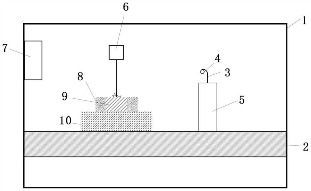
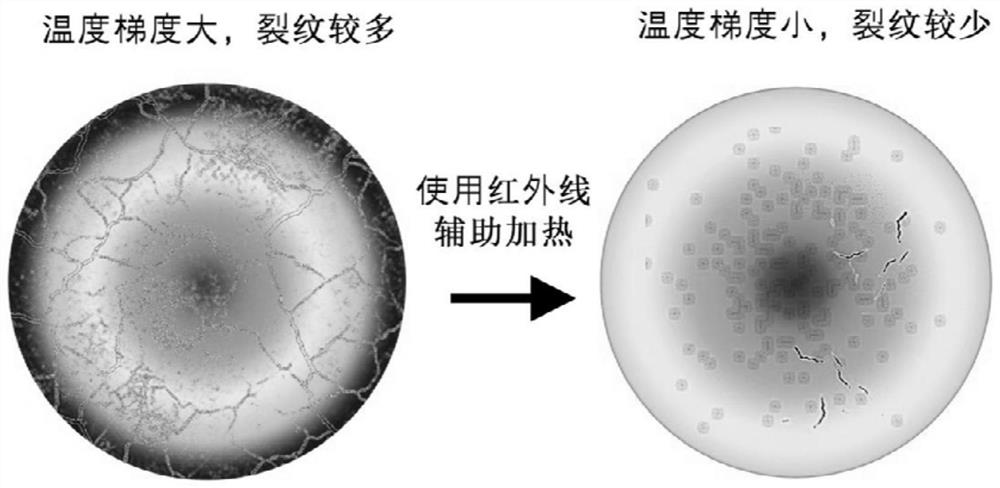

Image

  • Preparation method of laser additive manufacturing hot crack sensitive material based on infrared auxiliary preheating
  • Preparation method of laser additive manufacturing hot crack sensitive material based on infrared auxiliary preheating
  • Preparation method of laser additive manufacturing hot crack sensitive material based on infrared auxiliary preheating

Examples


Embodiment 1

[0042] (1) The composition of the aluminum-based alloy is that the Cu content is 3.6-4.5wt.%, the Li content is 0.7-1.1wt.%, the Mg content is 0.3-1.0wt.%, the Ag content is 0.3-0.8wt.%, and the Zr content is It is 0.1-0.2wt.%, the balance is Al, and the particle size of the powder is 25-53 μm.

[0043] (2) Use computer-aided design software to build a 3D solid geometric model of the target part and export it as an STL file, then use Materialise Magics software to slice the model in layers, and set the laser scanning path and laser process parameters. The laser process parameters are set as follows: the laser power is 250-350W, the laser scanning speed is 600-1000mm / s, the scanning spacing is 50μm, and the powder thickness is 30μm. The laser filling direction is rotated 37°.

[0044] (3) The slice file obtained in step (2) is imported into the computer control system of the transformed selective laser melting and forming equipment, and the aluminum-based alloy powder in step ...

Embodiment 2

[0048] (1) The composition of the tungsten-based alloy is that the Ni content is 5.8-7.2wt.%, the Fe content is 2.0-3.5wt.%, the Co content is 0.5-1.0wt.%, the balance is W, and the powder particle size is 15-45μm .

[0049] (2) Use computer-aided design software to build a 3D solid geometric model of the target part and export it as an STL file, then use Materialise Magics software to slice the model in layers, and set the laser scanning path and laser process parameters. The laser process parameters are set as follows: the laser power is 375-475W, the laser scanning speed is 400-600mm / s, the scanning distance is 50μm, and the powder thickness is 50μm. The partition scanning strategy is adopted, and the partition size is 5mm. The laser filling direction is rotated 37°.

[0050] (3) The slice file obtained in step (2) is imported into the computer control system of the transformed selective laser melting and forming equipment, and the aluminum-based alloy powder in step (1) i...

Embodiment 3

[0054] (1) The composition of nickel-based alloy is Cr content of 21.3-22.5wt.%, Fe content of 17.8-18.6wt.%, Mo content of 8.4-9.2wt.%, W content of 5.6-6.2wt.%, Co content It is 1.0-1.6 wt.%, the balance is Ni, and the particle size of the powder is 20-47 μm.

[0055] (2) Use computer-aided design software to build a 3D solid geometric model of the target part and export it as an STL file, then use Materialise Magics software to slice the model in layers, and set the laser scanning path and laser process parameters. The laser process parameters are set as follows: the laser power is 300-450W, the laser scanning speed is 1000-1400mm / s, the scanning distance is 50μm, and the powder thickness is 50μm. The laser filling direction is rotated 37°.

[0056] (3) The slice file obtained in step (2) is imported into the computer control system of the transformed selective laser melting and forming equipment, and the aluminum-based alloy powder in step (1) is placed in the laser addit...


PUM

PropertyMeasurementUnit
particle diameteraaaaaaaaaa

Abstract

The invention discloses a preparation method of a laser additive manufacturing hot crack sensitive material based on infrared auxiliary preheating. According to the method, in the process of laser additive manufacturing of hot crack sensitive materials such as aluminum-based alloy, tungsten-based alloy and nickel-based alloy, an infrared heat source is adopted for conducting preheating treatment on alloy powder. The infrared heat source can improve the preheating temperature of the laser to-be-scanned alloy powder, heat a specific area, reduce the temperature gradient of a molten pool and prolong the solidification time, so that the thermal stress concentration of a formed thermal crack sensitive material is reduced, the thermal cracking tendency of materials such as an aluminum-based alloy, a tungsten-based alloy and a nickel-based alloy in the laser forming process is reduced, and the laser forming quality is improved. And the laser additive manufacturing formability of the hot crack sensitive material and the quality of a formed part are improved. According to the method, the forming efficiency and the forming quality are synchronously improved, and laser additive manufacturing of hot crack sensitive materials such as high-quality formed aluminum-based, tungsten-based and nickel-based alloys becomes possible.

Description

technical field [0001] The invention belongs to the technical field of laser additive manufacturing, and relates to a preparation method for laser additive manufacturing of thermal crack sensitive materials based on infrared-assisted preheating. Background technique [0002] Laser additive manufacturing is based on the discrete-accumulation principle, which directly manufactures parts according to the three-dimensional model of the part. This method uses a high-energy laser beam to melt metal powder, and rapidly melts, solidifies and accumulates layer by layer to form a three-dimensional entity. High advantages, especially for the rapid manufacturing of small batches of components in aerospace products. Selective laser melting technology is an advanced laser additive manufacturing technology. This process uses a high-energy laser beam as a heat source to scan the metal powder bed layer by layer according to the scanning path planned in the 3D CAD slice model. , get the met...

Claims


Application Information

Patent Timeline
Patent Type & Authority Applications(China)
IPC IPC(8): B22F10/28B33Y10/00B33Y70/00C22C21/16C22C27/04C22C19/05B22F10/362B22F10/364B22F10/366B22F12/13B22F12/00B33Y30/00C22C1/04
CPCB22F10/28B33Y10/00B33Y70/00C22C21/16C22C27/04C22C19/055B22F10/362B22F10/364B22F10/366B22F12/13B22F12/00B33Y30/00C22C1/0416C22C1/045C22C1/0433Y02P10/25
Inventor 席丽霞顾冬冬陈龙冯丽莉王瑞琪罗棋胥紫微
Owner NANJING UNIV OF AERONAUTICS & ASTRONAUTICS
Learn More