
Flow controller and spent fuel aftertreatment system

A technology of flow controller and meter, which is applied in the direction of using electric device flow control, reactor fuel element, reducing greenhouse gas, etc., can solve the problems of radioactive material leakage, leakage, unreliable sealing method, etc., to achieve absolute sealing. Effect

Pending Publication Date: 2022-08-05
CHINA NUCLEAR POWER ENG CO LTD
View PDF0 Cites 0 Cited by
  • Summary
  • Abstract
  • Description
  • Claims
  • Application Information

AI Technical Summary

Problems solved by technology

[0003] In the prior art, a dynamic seal is used between the transmission shaft and the metering equipment. The sealing method is unreliable and prone to leakage, which easily leads to the leakage of radioactive substances.

Method used


Image

  • Flow controller and spent fuel aftertreatment system
  • Flow controller and spent fuel aftertreatment system
  • Flow controller and spent fuel aftertreatment system

Examples


Embodiment 1

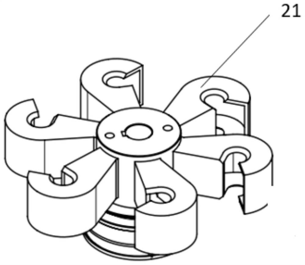
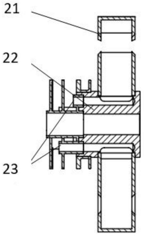
[0031] like figure 1 As shown, this embodiment discloses a flow controller, which includes a drive assembly 1, a transmission shaft assembly, an output shaft assembly, an isolation assembly and a doser 20. The drive assembly 1 is located outside the equipment room, and the transmission shaft assembly includes a transmission shaft 8 With the inner magnetic rotor 11, one end of the transmission shaft 8 is rotatably connected with the drive assembly 1, and the other end of the transmission shaft 8 extends into the equipment room through the wall 24 of the equipment room. Since the equipment room has the need to shield rays, the wall 24 The thickness of the transmission shaft 8 is set thicker, the setting length of the transmission shaft 8 also needs to be longer than the thickness of the wall 24, the transmission shaft 8 is cylindrical, the inner magnetic rotor 11 is installed at one end of the transmission shaft 8 located in the equipment room, and the output shaft assembly inclu...

Embodiment 2

[0055] The present invention also provides a spent fuel post-processing system, including an equipment room and the flow controller in Embodiment 1. The equipment room is used to isolate the drive assembly 1, and the flow controller is used to sample the feed liquid and measure the flow.

[0056] The drive assembly 1 is located outside the equipment room, and is connected to the output shaft 16 inside the equipment room through the transmission shaft 8, which is used to drive the transmission shaft 8 and the output shaft 16 to rotate, and then drives the quantizer 20 to rotate and sample, and complete the measurement of the material and liquid. Sampling and flow measurement.

[0057] The spent fuel post-processing system in this embodiment has the function of continuously and uniformly measuring and controlling the flow of the feed liquid.


PUM


Abstract

The invention discloses a flow controller and a spent fuel aftertreatment system comprising the flow controller, the flow controller comprises a driving assembly, a transmission shaft assembly, an output shaft assembly, an isolation assembly and a batcher, the driving assembly is arranged outside an equipment chamber, the transmission shaft assembly comprises a transmission shaft and an inner magnetic rotor, and the output shaft assembly comprises an output shaft and an output shaft; one end of the transmission shaft is rotationally connected with the driving assembly, the other end of the transmission shaft penetrates through the wall body of the equipment chamber and extends into the equipment chamber, the inner magnetic rotor is installed on the transmission shaft, the output shaft assembly comprises an output shaft and an outer magnetic rotor, the outer magnetic rotor is installed at one end of the output shaft, and the other end of the output shaft is connected with the batcher; the isolation assembly comprises a supporting sleeve and an isolation sleeve, the inner magnetic rotor and the outer magnetic rotor are both arranged in the supporting sleeve and are isolated through the isolation sleeve, and the driving assembly rotates to sequentially drive the transmission shaft and the output shaft to rotate so as to drive the batcher to rotate, so that quantitative sampling of fluid is completed. The flow controller has good sealing performance.

Description

technical field [0001] The invention belongs to the technical field of nuclear industry, and in particular relates to a flow controller and a spent fuel post-processing system including the flow controller. Background technique [0002] The continuous measurement and control of the small flow of liquid is an important process link in the spent fuel reprocessing project, and the small flow controller is one of the main equipment to realize the continuous measurement and control of the small flow. In some occasions where it is necessary to measure and control a small flow of feed liquid during the spent fuel reprocessing process, such as the equipment room, the space is filled with highly radioactive elements and alpha aerosols, so the tightness and isolation of the small flow controller are proposed. Higher requirements do not allow leakage at the seal, resulting in radioactive spillage. [0003] In the prior art, a dynamic seal is used between the transmission shaft and the...

Claims


Application Information

Patent Timeline
Patent Type & Authority Applications(China)
IPC IPC(8): G05D7/06G21C19/42
CPCG05D7/0617G21C19/42Y02E30/30
Inventor 洪圆冯存强刘晓莉李晓薇杨宏悦唐翊桐马世海李海丽张博任鸿斌臧少锋张皎丹杨庆彧吴珂杨颖姝
Owner CHINA NUCLEAR POWER ENG CO LTD
Learn More