
Hydraulic stroke transmitter

A hydraulic and stroke technology, applied in the field of hydraulic stroke transmitter, to achieve the effect of less loss

Active Publication Date: 2014-03-26
METISMOTION GMBH
View PDF5 Cites 0 Cited by
  • Summary
  • Abstract
  • Description
  • Claims
  • Application Information

AI Technical Summary

Problems solved by technology

Such guided pistons require high mechanical precision in machining and are prone to wear

Method used


Image

  • Hydraulic stroke transmitter
  • Hydraulic stroke transmitter
  • Hydraulic stroke transmitter

Examples


Embodiment Construction

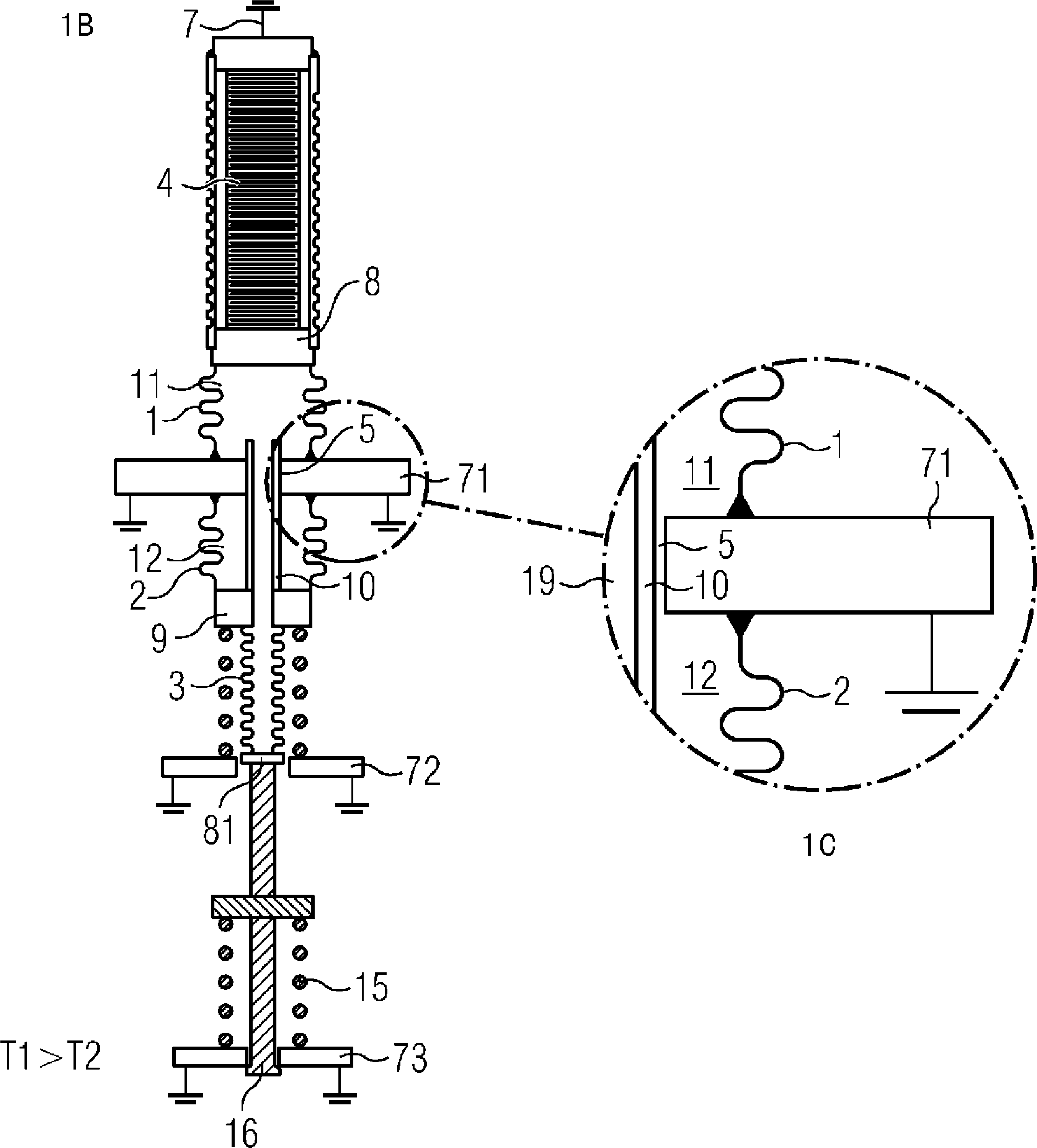
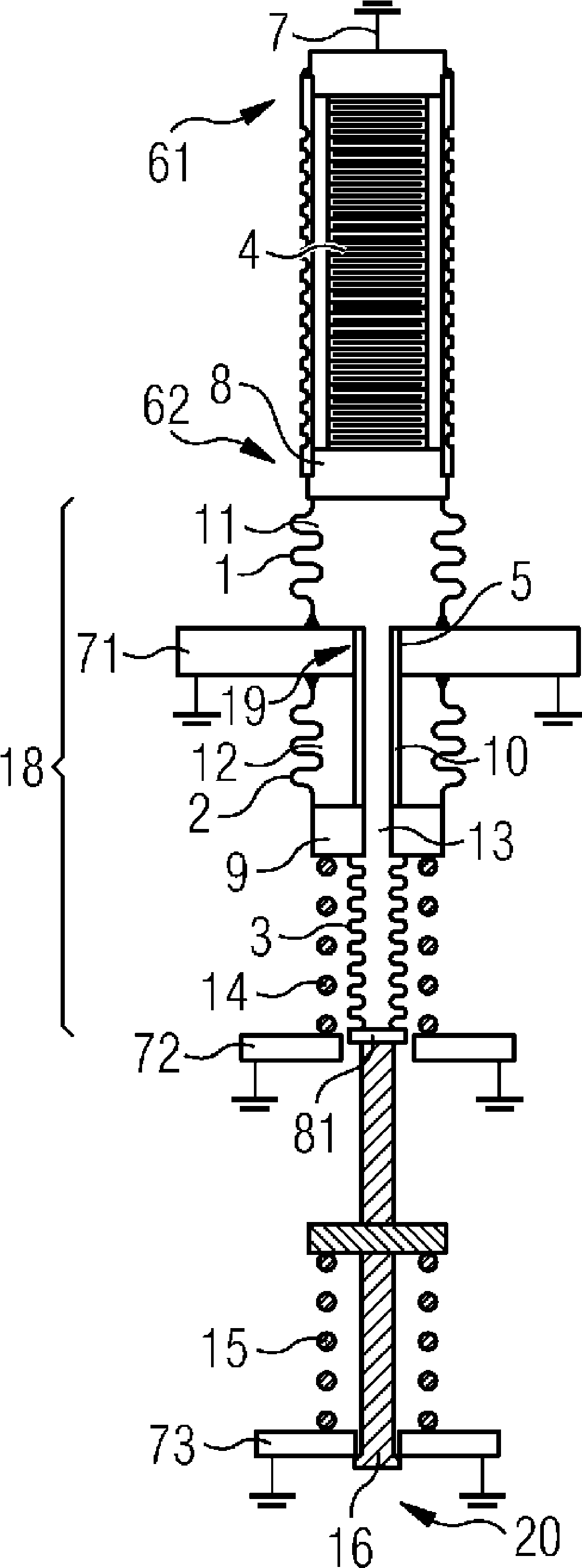
[0031] Figure 1A and 1B In principle the same structure is shown, where the Figure 1A There exists an operating temperature T1 in which the operating temperature T1 is greater than the corresponding Figure 1B The working temperature T2. The two figures have substantially the same structural components denoted by the same reference numerals. A solid-state actuator 4 is present here, which can be a piezoelectric actuator or a magnetostrictive actuator. The actuator is supported at the rear with its rear end 61 on the fixed bearing 7 . At the front end 62 of the solid-state actuator, the solid-state actuator has an end plate 8 which is preferably connected to the first metal bellows 1 by means of a weld. A first hydraulic volume 11 is shown here.

[0032] At its other end, the first metal bellows 1 is fixedly and gas-tightly connected to a fixed bearing 71, as seen in the axial direction of the solid-state actuator 4, preferably by means of a weld seam .

[0033] The fix...


PUM


Abstract

A stroke translator or an injector having a solid-state actuator for generating a stroke and a hydraulic system for the hydraulic transmission of the stroke of the solid-state actuator to a control element such as a jet needle of a valve. The hydraulic system has hydraulic volumes hermetically sealed to the outside by metal bellows and constitute a hydraulic bearing with compensation for play. The advantages over known hydraulic levers are such that a complete metal seal is provided, and that a lower-wear design can be realized. Furthermore, a modular structure can be produced.

Description

technical field [0001] The invention relates to a hydraulic stroke transmitter which transmits a stroke predetermined by a stationary actuator. In most cases, this results in a transmission for extending the otherwise small stroke of the solid-state actuator. Background technique [0002] In order to introduce the desired fuel quantity into any combustion process, injectors are generally required, by means of which the fuel quantity can be metered. Since many combustion processes are carried out with direct injection of fuel under high pressure, particularly fast-acting actuators are often used which drive the injectors. This means that the actuator generates a stroke which, for example, actuates the injector needle, which itself opens the valve and releases fuel at predetermined time intervals and with an adjustable flow rate for the combustion process. In this case the combustion air is supplied separately. [0003] Injectors for high-pressure direct injection often use...

Claims


Application Information

Patent Timeline
Patent Type & Authority Patents(China)
IPC IPC(8): F02M51/06F02M61/16
CPCF16K31/1221F02M61/167F16K41/10F02M51/0603
Inventor G.巴赫迈尔G.埃贝尔斯贝尔格B.菲舍尔M.格利希M.赫格W.泽尔斯
Owner METISMOTION GMBH
Learn More