Vacuum dispensing machine for processing electronic equipment

A technology of electronic equipment and glue dispenser, which is applied to the device and coating of the surface coating liquid, which can solve the problems of high output power requirements, reduced service life, unstable vacuum value, etc., to prolong the service life and prevent Effect of impact and improvement of airtightness

Active Publication Date: 2022-08-05
SUZHOU TERUITE ROBOT CO LTD
View PDF9 Cites 0 Cited by
  • Summary
  • Abstract
  • Description
  • Claims
  • Application Information

AI Technical Summary

Problems solved by technology

[0004] In the prior art, when the chamber is evacuated, due to the large pressure difference between the air pressure in the chamber and the outside air pressure, and the time delay when the valve is closed, the vacuum value in the chamber will be unstable.
Moreover, the adsorption force generated by the large internal and external pressure difference has a high output power requirement for the valve closing mechanism, and the valve opening and closing mechanism with large kinetic energy will cause impact on the cavity and reduce its service life.

Method used


Image

  • Vacuum dispensing machine for processing electronic equipment
  • Vacuum dispensing machine for processing electronic equipment
  • Vacuum dispensing machine for processing electronic equipment

Examples


Embodiment 1

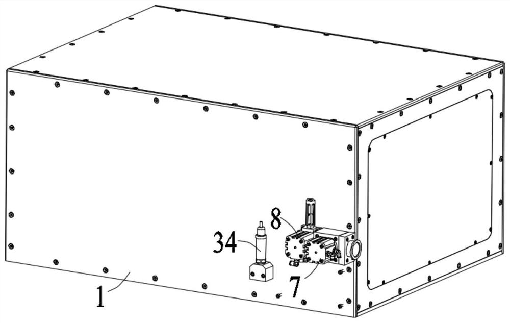
[0039] Example 1: A vacuum dispenser for electronic equipment processing, including a vacuum chamber body 1, a frame 16, a dispensing valve 17 and a workbench 18, the vacuum chamber body 1 is installed on the frame 16, and the point The glue valve 17 and the workbench 18 are both located in the vacuum chamber body 1, and the glue dispensing valve 17 is located directly above the workbench 18;

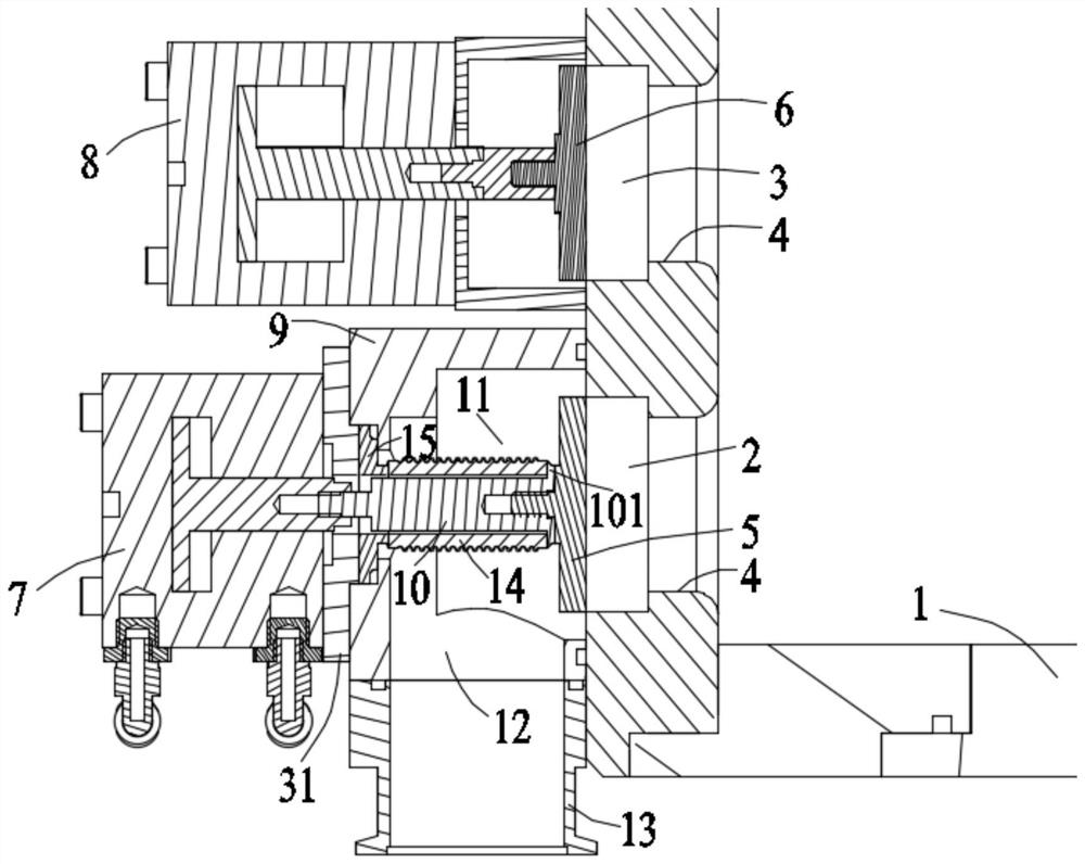
[0040] The outer surface of one side of the vacuum chamber body 1 is provided with an air suction port 2 and an air inlet port 3. The air suction port 2 and the air inlet port 3 each have a diameter on the inner wall near the inner end of the vacuum chamber body 1. For the flange portion 4 protruding inward, a first flange 5 is embedded in the air inlet 2, a second flange 6 is embedded in the air inlet 3, and the first flange 5 is embedded in the air inlet 3. , The end face of each end of the second flange 6 is in contact with the end face of the corresponding flange portion 4, and the ...

Embodiment 2

[0055] Example 2: A vacuum dispensing machine for electronic equipment processing, including a vacuum chamber body 1, a frame 16, a dispensing valve 17 and a workbench 18, the vacuum chamber body 1 is installed on the frame 16, and the point The glue valve 17 and the workbench 18 are both located in the vacuum chamber body 1, and the glue dispensing valve 17 is located directly above the workbench 18;

[0056] The outer surface of one side of the vacuum chamber body 1 is provided with an air suction port 2 and an air inlet port 3. The air suction port 2 and the air inlet port 3 each have a diameter on the inner wall near the inner end of the vacuum chamber body 1. For the flange portion 4 protruding inward, a first flange 5 is embedded in the air inlet 2, a second flange 6 is embedded in the air inlet 3, and the first flange 5 is embedded in the air inlet 3. , The end face of each end of the second flange 6 is in contact with the end face of the corresponding flange portion 4,...


PUM


Abstract

The invention discloses a vacuum dispensing machine for electronic equipment processing, which comprises a vacuum bin body, a rack, a dispensing valve and a workbench, the outer surface of one side of the vacuum bin body is provided with an air extraction opening and an air inlet, when a first air cylinder pulls a first flange plate open from the air extraction opening, an external connection air pump starts to work, and when a second air cylinder pulls a second flange plate open from the air extraction opening, the vacuum bin body is opened; pumping air in the vacuum bin body; when the air pressure of the vacuum bin body is greater than a preset value of an air pressure sensor mounted on the vacuum bin body, the first air cylinder pushes the first flange plate into the extraction opening; the second flange plate is pulled open from the air inlet, and the air pressure in the vacuum bin body is adjusted till the air pressure reaches a preset value; and after the operation of the vacuum bin body is completed, the second flange plate is pulled open from the air inlet, and pressure relief is carried out. The sealing performance of the first flange plate to the extraction opening in the long-term use process can be improved, impact caused by too fast contraction in the opening process of the first flange plate can be prevented, and the service life of the mechanism is prolonged.

Description

technical field [0001] The invention relates to the technical field of vacuum cavity sealing, in particular to a vacuum dispensing machine for processing electronic equipment. Background technique [0002] At present, smart electronic devices are developing rapidly, such as smart phones and tablet computers. With the advancement of technology, various smart electronic devices have more and more functions. Therefore, the integration of smart electronic device functions promotes the gradual increase of various components. The connection method between parts has also changed from the previous lock screw to the glue connection. In the non-vacuum working environment of the glue dispenser, the air before and after the glue drips onto the product has the opportunity to enter the glue, which directly affects the quality of the product. [0003] The vacuum chamber is mainly used in the field of product dispensing and packaging. Using the force of negative pressure, the air in the va...

Claims


Application Information

Patent Timeline
Patent Type & Authority Applications(China)
IPC IPC(8): B05C5/02B05C15/00B05C11/00
CPCB05C11/00B05C5/0212B05C15/00
Inventor 陈晓峰杨春雨
Owner SUZHOU TERUITE ROBOT CO LTD
Why Eureka
Try Eureka