
Method for eliminating optical interval adjustment error by using optical lens with turning light path

A technology of optical lens and refracting optical path, which is applied in the direction of optics, optical components, optical instrument testing, etc., can solve the problems that the focal length cannot meet the requirements, the interval cannot be measured and adjusted, and the operation process is complicated, so as to achieve objective and true results and improve the adjustment. Efficiency and debugging accuracy, the effect of high measurement accuracy

Pending Publication Date: 2022-07-29
西安应用光学研究所
View PDF0 Cites 1 Cited by
  • Summary
  • Abstract
  • Description
  • Claims
  • Application Information

AI Technical Summary

Problems solved by technology

Therefore, the optical distance between the front mirror group and the rear mirror group in the refracted optical path can usually only be guaranteed by structural processing, and because the distance cannot be measured and adjusted, there is often a uniform halo in the system imaging, and the focal length often cannot meet the requirements. Require
In the paper "Research on the Application of Mirror Positioner in the Refracted Optical System" published by Qu Liang in the third issue of 2020, the author mentioned that the mirror locator can be used to measure the mirror optical distance of the refracted optical system, although this method The measurement accuracy is high, but the measurement equipment is imported, the price is expensive, and the operation process is relatively complicated, so it is difficult to widely promote

Method used


Image

  • Method for eliminating optical interval adjustment error by using optical lens with turning light path
  • Method for eliminating optical interval adjustment error by using optical lens with turning light path

Examples


Embodiment 1

[0051] The method for eliminating the optical spacing adjustment error of an optical lens with a refracted optical path proposed in this embodiment includes the following steps:

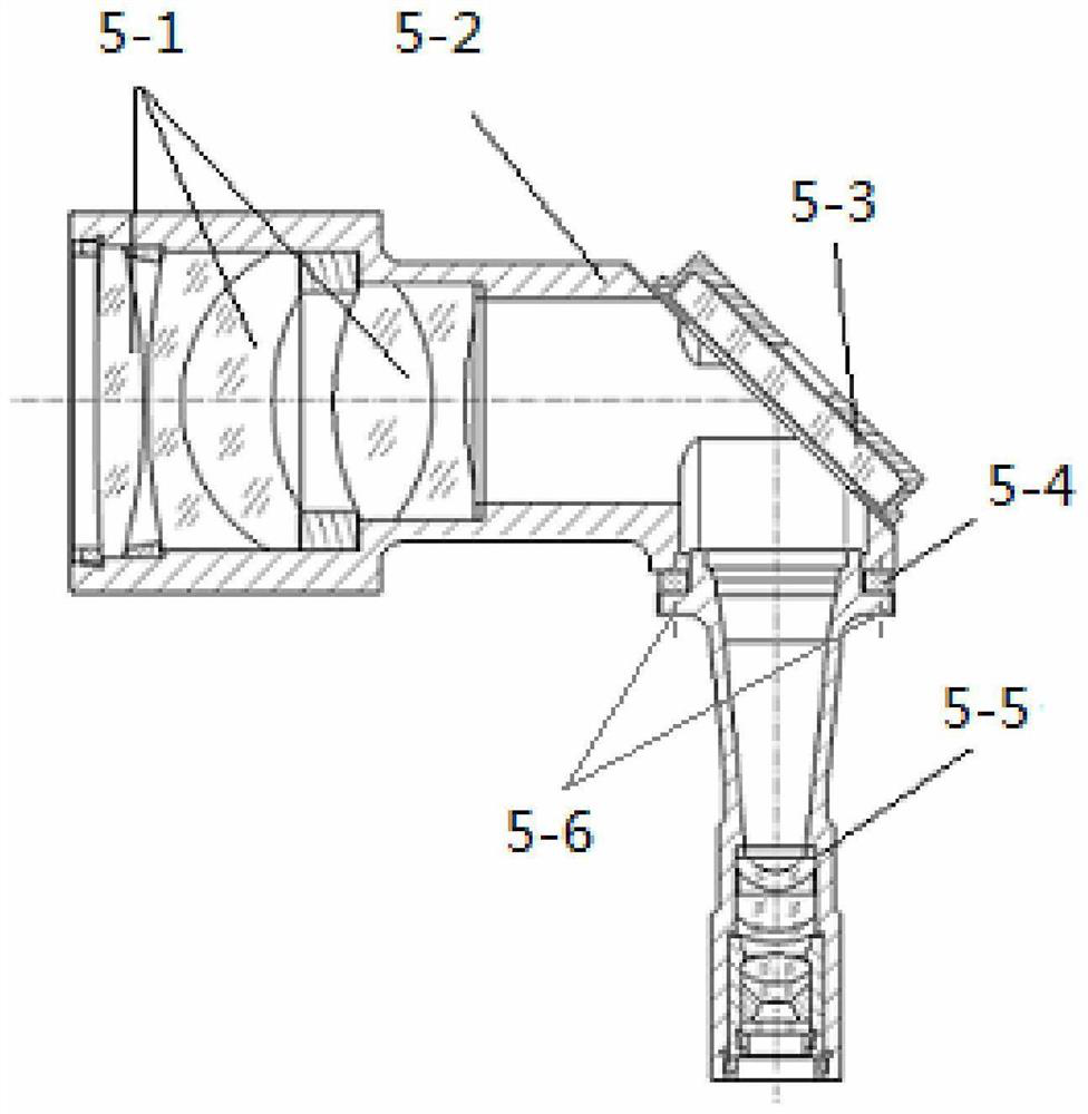
[0052] Step 1: The folded optical path optical lens consists of a folded mirror frame 5-2, a front mirror group 5-1, a rear mirror group 5-5, a flat mirror group 5-3 and an adjustment spacer 5-4, etc. The flat mirror group 5-3 is fixed to the installation position of the folding mirror frame 5-2, and the flat mirror surface 5-3 and the central axis of the folding mirror frame 5-2 are required to be installed at 45° without stress deformation. The lenses in the mirror group 5-1 are installed in the folding mirror frame 5-2 according to the requirements of the drawing and are fixed reliably. Finally, put the rear mirror group 5-5 together with the adjusting spacer 5-4 into the folding mirror frame 5-2 at the same time, and use the connecting screws 5-6 to fasten them.

[0053] Step 2: The folded optic...


PUM


Abstract

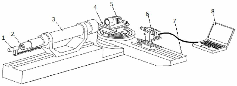
The invention belongs to the technical field of optical machine installation and adjustment, and particularly relates to a method for eliminating optical interval installation and adjustment errors by using an optical lens with a reflex optical path, which utilizes a collimator, a star point reticle, a lighting device, a lifting adjustable platform, a CCD (Charge Coupled Device) image sensor with a microscope lens, a high-resolution display and the like. An optical interval error between a front lens group and a rear lens group of the light path reflex optical lens is accurately eliminated by using an aberration theory, and the device has the advantages that the change of the interval between the front lens group and the rear lens group of the light path reflex optical lens can be clearly displayed through a high-resolution display; and the interval error between the front lens group and the rear lens group is judged according to the spherical aberration change condition reflected by the star point diffraction image, and the method has the characteristics of simplicity and intuition in operation, high installation and adjustment precision and the like.

Description

technical field [0001] The invention belongs to the technical field of optical-mechanical adjustment, and in particular relates to a method for eliminating an optical interval adjustment error with an optical lens with a folded optical path. Background technique [0002] In the design of new optoelectronic systems, in order to meet the requirements of miniaturization and light weight, it is often necessary to fold the optical path. The common structural form is that the front mirror group and the rear mirror group are respectively installed in the folding mirror frame, and installed to the theoretical position through a flat reflector to achieve the required folding angle and make the front mirror group and the rear mirror group. The optical axis is coaxial. At this time, the theoretical distance between the front mirror group and the rear mirror group needs to meet the requirements to obtain a good comprehensive imaging effect and meet the design values ​​of optical indicat...

Claims


Application Information

Patent Timeline
Patent Type & Authority Applications(China)
IPC IPC(8): G02B27/62G02B21/36G01M11/00
CPCG02B27/62G02B21/361G02B21/362G01M11/00
Inventor 张向明孔龙阳赵红军许航航马力阮越李阳杜萌
Owner 西安应用光学研究所
Learn More