Railway line component laying and replacing gantry crane device and operation method thereof

A line component and door crane technology, which is applied in roads, track laying, transportation and packaging, etc., can solve the problems of difficulty in adapting to the operation requirements of railway lines, the existence of operation safety risks, and the occupation of space adjacent to the line, so as to achieve small space occupation and high quality. Lightweight and improved work efficiency

Pending Publication Date: 2022-07-29
ZHUZHOU TIMES ELECTRONICS TECH CO LTD
View PDF5 Cites 3 Cited by
  • Summary
  • Abstract
  • Description
  • Claims
  • Application Information

AI Technical Summary

Problems solved by technology

[0009] In view of this, the purpose of the present invention is to provide a door crane device for railway line component replacement and its operation method to solve the problem that existing railway line component replacement methods occupy adjacent line space, have operational safety risks, inflexible operation, and difficult Technical Problems Adapting to the Operational Requirements of Railway Lines under Complicated Working Conditions

Method used


Image

  • Railway line component laying and replacing gantry crane device and operation method thereof
  • Railway line component laying and replacing gantry crane device and operation method thereof
  • Railway line component laying and replacing gantry crane device and operation method thereof

Examples


Embodiment 1

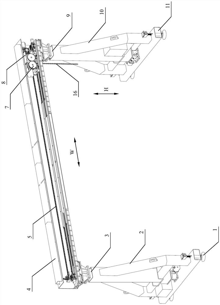
[0063] as attached figure 1 As shown, an embodiment of the door hanging device 100 for laying and replacing railway line components of the present invention specifically includes:

[0064] truss 4;

[0065] It is arranged on the truss 4 and can be carried out laterally along the truss 4 (as attached figure 1 The traverse travel mechanism 8 that moves in the direction shown in W) to adjust the hoisting position; the traverse travel mechanism 8 includes a lifting mechanism 7, and the lifting mechanism 7 can drive the chain 16 to lift and move vertically, and the end of the chain 16 is set There is a hook 6, and the hook 6 is further connected with a spreader 700, and is clamped by the spreader 700 to realize the transportation of railway line components;

[0066] The left and right legs are respectively movably arranged on the lower parts of the left and right ends of the truss 4 , and the left and right legs can move laterally along the truss 4 to adjust the lateral span of t...

Embodiment 2

[0077] as attached Figure 10 As shown, it is a schematic diagram of the transportation structure of the door hanger 100 of the present invention described in Embodiment 1 on the rail flat car. On the lifting platform 200, the lifting platform 200 has functions of lifting and rotating. A new line component 500 for replacement is placed on the second flat car 400 . The door hanger 100 placed on the first flat car 300 and the new line component 500 placed on the second flat car 400 are transported to the construction area by the rail car 1000 powered. After arriving at the designated construction area, the door hanging device 100 places the outriggers on both lateral sides of the door hanging device 100 with the specified designation of the roadbed 900 on both sides of the basic rail 800 of the line through the lifting and rotating actions of the lifting platform 200 on the first flat car 300 . area.

Embodiment 3

[0079] as attached Figure 11 As shown in the figure, an embodiment of the operation method of the door hanging device for laying and replacing the railway line components of the present invention as described in Embodiment 1 specifically includes the following steps:

[0080] S101) The door hanger 100 retracts the left and right legs, and is fixed on the first flat car 300 and transported to the work site, as shown in the attached Figure 12 shown;

[0081] S102) After arriving at the construction site, deploy the door hanging device 100 through the lifting platform 200, the left and right outriggers of the door hanging device 100 are extended and supported to the working surface 900, the horizontality of the truss 4 is adjusted, the first flat car 300 withdraw, as attached Figure 13 shown;

[0082] S103) The door hoisting device 100 hoists the new line component 500 placed on the second flat car 400 and transported below it, and the second flat car 400 is withdrawn, as s...


PUM


Abstract

The invention discloses a railway line component laying and replacing gantry crane device and an operation method thereof. The device comprises a truss; the transverse moving walking mechanism is arranged on the truss, can transversely move along the truss and is used for adjusting the hoisting position; the transverse moving walking mechanism comprises a lifting mechanism, and the lifting mechanism can drive the loop chain to ascend and descend in the vertical direction so as to carry railway line components. The left supporting leg and the right supporting leg are movably arranged on the lower portions of the left end and the right end of the truss respectively, and the left supporting leg and the right supporting leg can transversely move along the truss so as to adjust the transverse span of the gantry crane device. The left supporting leg and the right supporting leg can ascend and descend in the vertical direction so as to adjust the height from the truss to the working face. The technical problems that an existing railway line component replacement mode occupies the space of an adjacent line, operation safety risks exist, operation is not flexible, and the operation requirement under the complex working condition of the railway line is difficult to meet can be solved.

Description

technical field [0001] The invention relates to the technical field of railway construction machinery, in particular to a door hoisting device for laying, replacing and hoisting railway line components and an operation method thereof. Background technique [0002] At present, the mileage of high-speed railways in my country has reached 35,000 kilometers, and the transport capacity has reached 70% of the total passenger traffic. Its normal operation has an increasing impact on national travel and business activities. Therefore, the on-site lifting, replacement and maintenance of high-speed rail line components has become the top priority of technology in the field of track construction machinery line maintenance. At present, railway line components are mainly lifted and replaced by rail cranes and cantilever crane equipment. For the replacement of long and heavy line components, such as steel rails, pointed rails, turnouts and other components, when multiple rail cranes are ...

Claims


Application Information

Patent Timeline
Patent Type & Authority Applications(China)
IPC IPC(8): E01B29/04E01B29/06E01B29/16B66C19/00B66C11/16B66C7/00B66C9/14
CPCE01B29/04E01B29/06E01B29/16B66C19/00B66C11/16B66C7/00B66C9/14
Inventor 陈亮陪李石平牛学信王鹏举晏红文盛智勇李波
Owner ZHUZHOU TIMES ELECTRONICS TECH CO LTD
Why Eureka
Try Eureka