Energy-saving circulating system for sand-to-sand heat exchange grinding
A circulation system and heat exchange tube technology, applied in lighting and heating equipment, machinery for cleaning/processing casting mold materials, casting molding equipment, etc., can solve problems such as high cost of production line, waste of high-temperature waste heat, and difficulty in heat recovery , to achieve efficient utilization, sufficient purification treatment, and good treatment effect
- Summary
- Abstract
- Description
- Claims
- Application Information
AI Technical Summary
Problems solved by technology
Method used
Image
Examples
Embodiment 1
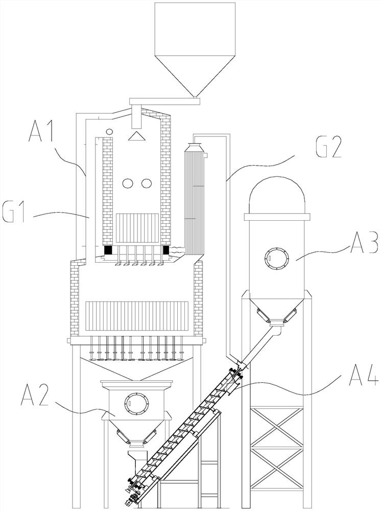
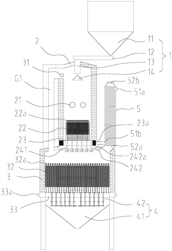
[0084] like Figure 1-Figure 11 As shown, an energy-saving circulatory system for sand-to-sand heat exchange grinding includes a roaster A1, a hot sand tank A2, a heat exchange grinding device A3 and a wet sand tank A4,
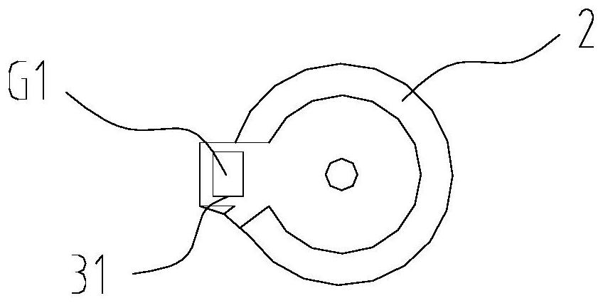
[0085] The top of the roasting furnace A1 is provided with a feeding mechanism 1, the interior of the roasting furnace A1 is sequentially provided with a primary combustion chamber 2, a secondary combustion chamber 3 and a charging mechanism 4 from top to bottom, and the bottom of the roasting furnace A1 is provided with several A support foot is used to support the whole roasting furnace A1;
[0086] In this embodiment, the side walls of the primary combustion chamber 2 and the secondary combustion chamber 3 are sequentially composed of refractory bricks, thermal insulation rock wool and shells from the inside to the outside. The side walls of the primary combustion chamber 2 and the secondary combustion chamber 3 can effectively ensure that when the roasti...
Embodiment 2
[0138] One of the embodiments of the present invention, the main technical solution of this embodiment and the features of Embodiment 1, which are not explained in this embodiment, are explained in Embodiment 1, and will not be repeated here. The difference between this embodiment and Embodiment 1 is:
[0139] In this embodiment, the driving wheel 742 is a driving gear, the driven wheel 743 is a driven gear, and the driving connection is formed by meshing between the driving wheel 742 and the driven wheel 743;
[0140] The motor 741 drives the inner cylinder 72 to rotate relative to the outer cylinder 71 through the meshing transmission of the driving gear and the driven gear, so that the structure of the driving assembly 74 is more compact. When the motor 741 outputs torque, the driving gear and the driven gear are precisely meshed, resulting in The noise is low, which is beneficial to prolong the actual service life of the large heat exchange grinding equipment A3.
Embodiment 3
[0142] One of the embodiments of the present invention, the main technical solution of this embodiment and the features of Embodiment 1, which are not explained in this embodiment, are explained in Embodiment 1, and will not be repeated here. The difference between this embodiment and Embodiment 1 is:
[0143] In this embodiment, a shock absorber 744 is further disposed between the driving assembly 74 and the frame 6 , and the shock absorber 744 includes a fixed seat 7441 and a plurality of plastic columns 7442 connected to each other. The driving assembly 74 It is fixedly connected to the fixed seat 7441 and is fixedly connected to the frame 6 through the plurality of plastic columns 7442; in order to improve the transmission efficiency of the drive assembly 74, further, a reducer is arranged between the drive assembly 74 and the frame 6. The vibrator 744 can remove the vibration of the drive assembly 74 and effectively prolong the service life of the drive assembly 74 .
PUM
 Abstract
Description
Claims
Application Information
 - Generate Ideas
- Intellectual Property
- Life Sciences
- Materials
- Tech Scout
- Unparalleled Data Quality
- Higher Quality Content
- 60% Fewer Hallucinations
Browse by: Latest US Patents, China's latest patents, Technical Efficacy Thesaurus, Application Domain, Technology Topic, Popular Technical Reports.
© 2025 PatSnap. All rights reserved.Legal|Privacy policy|Modern Slavery Act Transparency Statement|Sitemap|About US| Contact US: help@patsnap.com


