
Efficient mineral separation device for tunnel excavation

A tunnel excavation, high-efficiency technology, applied in the direction of cleaning method, cleaning method and utensils, grain processing, etc. using gas flow, can solve the problem of poor grinding effect, achieve the effect of reducing adhesion and preventing clogging

Pending Publication Date: 2022-07-29
扬州市森木机械有限公司
View PDF0 Cites 0 Cited by
  • Summary
  • Abstract
  • Description
  • Claims
  • Application Information

AI Technical Summary

Problems solved by technology

The machinery that implements this process is called mineral processing machinery. According to the mineral processing process, mineral processing machinery is divided into crushing, grinding, screening, sorting (sorting) and dehydration machinery. In recent years, ball mills are the most common and most versatile grinding equipment. , the ball mill completes the crushing effect on the material by the impact and grinding effect of the medium on the material. In the mechanical process of the crushing of the material by the medium, the medium acts as an energy medium to convert the external energy into a crushing force on the material. The material is crushed. In the process of crushing the mineral material by the ball mill, if the particle size of the crushed material is small, the mineral material powder will adhere to the internal lining plate, and the impact of the subsequent grinding ball on the mineral material will be eliminated. Mineral powder absorbs energy, resulting in poor grinding effect, so a device is needed to reduce the adhesion of mineral powder on the lining board

Method used


Image

  • Efficient mineral separation device for tunnel excavation
  • Efficient mineral separation device for tunnel excavation
  • Efficient mineral separation device for tunnel excavation

Examples


Embodiment Construction

[0024] The technical solutions in the embodiments of the present invention will be clearly and completely described below with reference to the accompanying drawings in the embodiments of the present invention. Obviously, the described embodiments are only a part of the embodiments of the present invention, but not all of the embodiments.

[0025] Examples of such embodiments are illustrated in the accompanying drawings, wherein the same or similar reference numerals refer to the same or similar elements or elements having the same or similar functions throughout. The embodiments described below with reference to the accompanying drawings are exemplary, and are intended to explain the present invention and should not be construed as limiting the present invention.

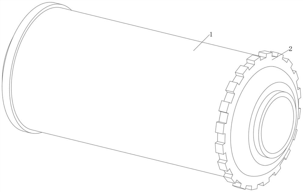
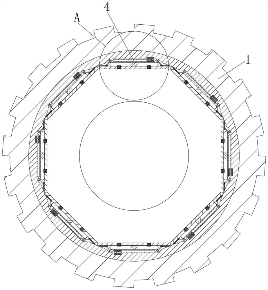
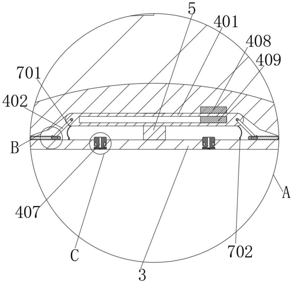
[0026] see Figure 1-6 , The present invention provides a technical solution: a high-efficiency mineral processing device for tunnel excavation, comprising a crushing cylinder 1, the outer wall of the crushing cyli...


PUM


Abstract

The invention discloses an efficient mineral separation device for tunnel excavation, and relates to the technical field of tunnel excavation. The efficient mineral separation device for tunnel excavation comprises a smashing cylinder, a gear is fixedly connected to the outer wall of the smashing cylinder, a lining plate is fixedly connected to the inner wall of the smashing cylinder, an anti-adhesion mechanism is arranged between the smashing cylinder and the lining plate, and the upper end and the lower end of a connecting column are fixedly connected with the inner wall of the smashing cylinder and the outer wall of the lining plate correspondingly. According to the efficient mineral separation device for tunnel excavation, when the crushing cylinder rotates, a vibrating plate can be driven to rotate, so that when the vibrating plate rotates to the upper side of a lining plate, due to the fact that the vibrating plate is vertically downward and is not affected by the inner wall of the crushing cylinder, the force is the maximum, and the vibrating plate can press a sliding block downwards to enable the sliding block to extrude a limiting soft rod out of a sliding rail; therefore, the vibrating plate rapidly falls down to impact the outer wall of the lining plate, mineral powder adhered to the lining plate is shaken off, and the mineral powder adhered to the lining plate is reduced.

Description

technical field [0001] The invention relates to the technical field of tunnel excavation, in particular to a high-efficiency mineral processing device for tunnel excavation. Background technique [0002] Mineral beneficiation is the process of selecting useful minerals from the collected mineral raw materials according to the differences in physical properties, physicochemical properties and chemical properties of various minerals. The machinery that implements this process is called mineral processing machinery. According to the mineral processing process, mineral processing machinery is divided into crushing, grinding, screening, sorting (sorting) and dewatering machinery. In recent years, ball mills are the most common and versatile grinding equipment. , The ball mill completes the crushing effect of the material by the impact and grinding of the medium on the material. In the process of the crushing mechanics of the medium to the material, the medium as the medium of ene...

Claims


Application Information

Patent Timeline
IPC IPC(8): B02C17/10B02C17/18B02C17/22B08B7/02B08B5/02B02C23/24
CPCB02C17/10B02C17/18B02C17/22B08B7/02B08B5/02B02C23/24
Inventor 张小平
Owner 扬州市森木机械有限公司
Learn More