Eureka AIR delivers breakthrough ideas for toughest innovation challenges, trusted by R&D personnel around the world.

Edge network node deployment method and system for automobile welding workshop

An edge network and node deployment technology, applied in network topology, transmission system, network planning, etc., can solve the problems of remote smart devices, increased deployment costs, and poor communication quality, so as to avoid high hardware deployment costs and reduce solution complexity , the effect of speeding up the operation

Active Publication Date: 2022-07-26
XI AN JIAOTONG UNIV
View PDF9 Cites 0 Cited by
  • Summary
  • Abstract
  • Description
  • Claims
  • Application Information

AI Technical Summary

Problems solved by technology

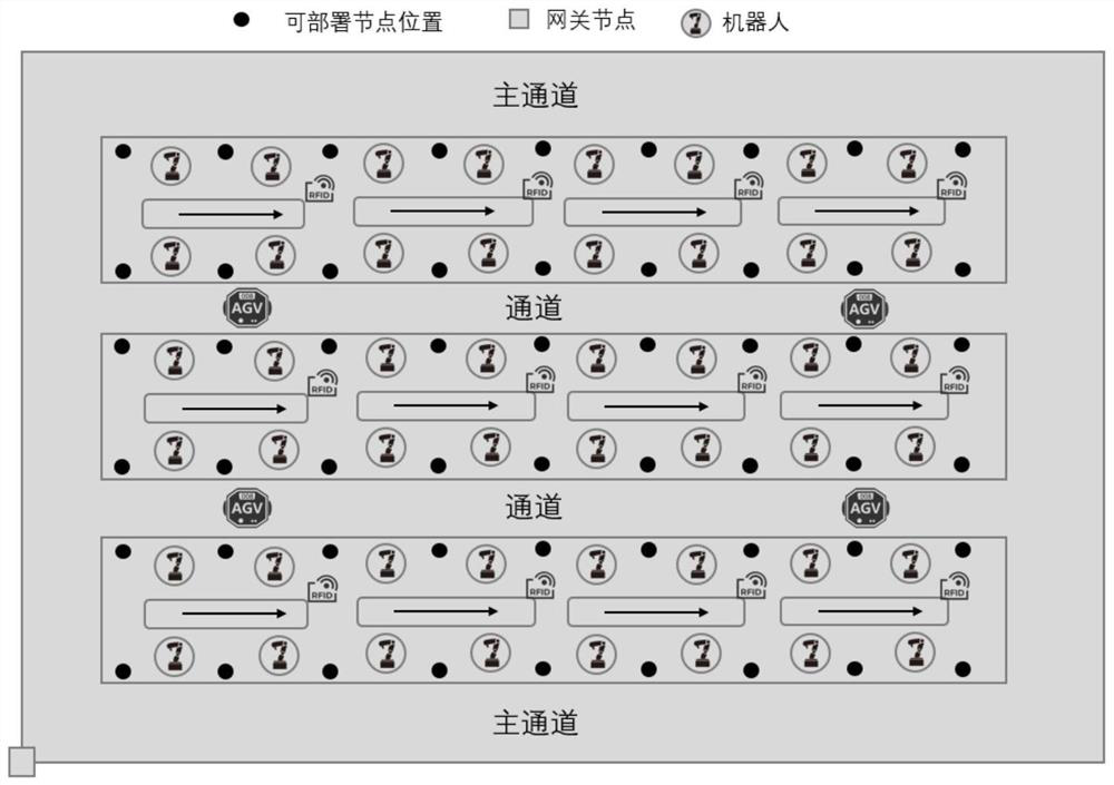
However, at present, the deployment of edge computing nodes in the body shop is generally based on expert experience to select a suitable layout location or random deployment. This method is difficult to choose the best edge node deployment location, which can easily cause the following problems:
[0004] 1) Too many edge computing nodes are deployed, resulting in waste of resources and increased deployment costs;
[0005] 2) The deployment location of edge computing nodes is unreasonable. Some edge computing nodes are responsible for more smart devices, and some edge computing nodes are responsible for fewer smart devices, resulting in unbalanced device load and affecting the service life of devices;
[0006] 3) The edge device is far away from the smart device, which cannot meet the real-time requirements of the device's computing tasks or the communication quality is too poor, etc.
[0007] At the same time, the data that these devices need to calculate and process varies according to different tasks, and the time sensitivity requirements for data processing are also different. Therefore, meeting the different requirements of different devices for task data processing also gives The deployment of edge computing nodes brings certain difficulties

Method used


Image

  • Edge network node deployment method and system for automobile welding workshop
  • Edge network node deployment method and system for automobile welding workshop
  • Edge network node deployment method and system for automobile welding workshop

Examples


Embodiment Construction

[0084] The technical solutions in the embodiments of the present invention will be clearly and completely described below with reference to the accompanying drawings in the embodiments of the present invention. Obviously, the described embodiments are part of the embodiments of the present invention, but not all of the embodiments. Based on the embodiments of the present invention, all other embodiments obtained by those of ordinary skill in the art without creative efforts shall fall within the protection scope of the present invention.

[0085] In the description of the present invention, it is to be understood that the terms "comprising" and "comprising" indicate the presence of the described features, integers, steps, operations, elements and / or components, but do not exclude one or more other features, The existence or addition of a whole, step, operation, element, component, and / or a collection thereof.

[0086] It should also be understood that the terminology used in t...


PUM


Abstract

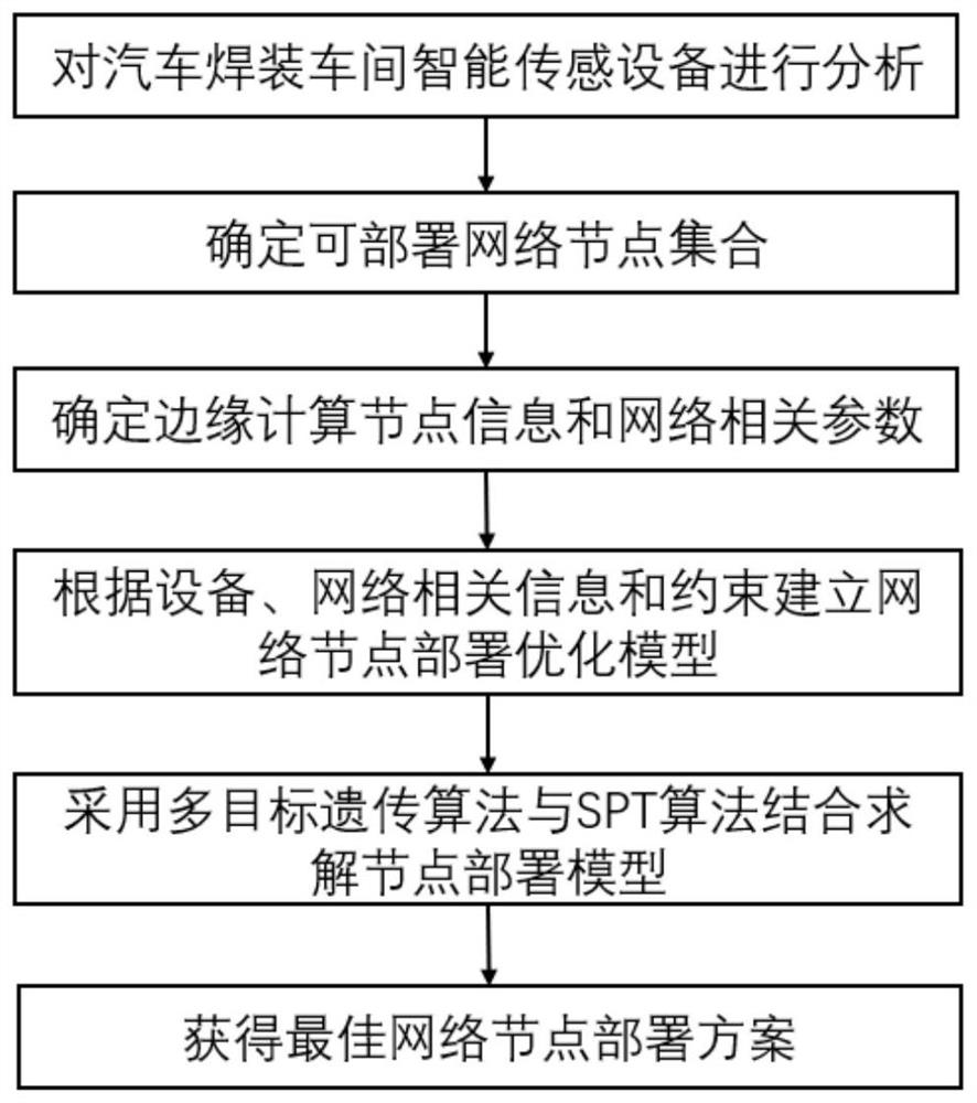
The invention discloses an edge network node deployment method and system for an automobile welding workshop, and the method comprises the steps: analyzing intelligent sensing equipment of the automobile welding workshop, and determining a deployable network node set, edge computing node equipment information and network parameter information; establishing a network node deployment multi-target optimization model according to the equipment, the network related information and the constraint relationship, and solving the network model by adopting the combination of a multi-target genetic algorithm and an SPT algorithm to obtain an optimal network node deployment scheme; the method overcomes the defects of unreasonable artificial experience and random deployment of network node positions, and optimizes multiple targets of intelligent sensing equipment calculation time delay, network hardware deployment cost and edge calculation node load balancing; in addition, time sensitivity requirements of different intelligent sensing devices on task calculation are considered, so that network node deployment is more reasonable.

Description

technical field [0001] The invention belongs to the technical field of network communication node deployment, and in particular relates to an edge network node deployment method and system for an automobile welding workshop. Background technique [0002] In the context of Industry 4.0, automobile production workshops are constantly developing towards intelligence and informatization, and more and more intelligent equipment sensing devices are added, making production workshops more intelligent and informatized, while generating a huge amount of data , which imposes huge storage, computing and transmission pressure on traditional cloud computing solutions. The traditional cloud computing solution not only fails to meet the real-time requirements of the production workshop for data processing, but also may cause the leakage of sensitive data inside the workshop, which is not conducive to data security. In order to solve this problem, edge computing has attracted the attention...

Claims


Application Information

Patent Timeline
Patent Type & Authority Applications(China)
IPC IPC(8): H04W16/18H04W16/22H04W28/08H04W84/18H04W88/04H04L67/10
CPCH04W16/18H04W16/22H04W28/08H04W84/18H04W88/04H04L67/10Y02D30/70
Inventor 周光辉李锦涛常丰田张超
Owner XI AN JIAOTONG UNIV
Why Eureka
Eureka Blog
Learn More