Traffic signal lamp system based on mathematical analysis model and control method thereof

A technology of traffic lights and mathematical analysis, which is applied in the field of traffic lights system and its control based on mathematical analysis models, can solve the problems of complex steps, inaccurate calculations, and lack of power protection, etc. Calculate the effect of high precision

Pending Publication Date: 2022-07-26
HARBIN CAMBRIDGE UNIV
View PDF0 Cites 0 Cited by
  • Summary
  • Abstract
  • Description
  • Claims
  • Application Information

AI Technical Summary

Problems solved by technology

[0004] The purpose of the present invention is to provide a traffic signal light system based on a mathematical analysis model and its control method, to solve the problem that the control method proposed in the above background technology is not convenient for remote monitoring of dust concentration and air temperature and humidity values, and does not have the function of power protection , the method steps are complicated, the calculation is not accurate enough, and the problem that it cannot be widely used

Method used


Image

  • Traffic signal lamp system based on mathematical analysis model and control method thereof
  • Traffic signal lamp system based on mathematical analysis model and control method thereof
  • Traffic signal lamp system based on mathematical analysis model and control method thereof

Examples


Embodiment 1

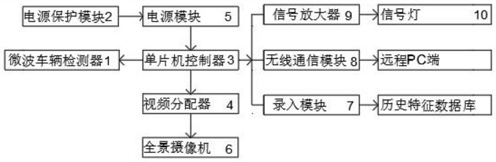
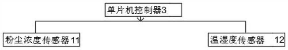
[0026] like Figure 1-3 As shown, a traffic signal system based on a mathematical analysis model includes a single-chip controller 3, a wireless communication module 8, a video distributor 4, a power protection module 2 and an input module 7. The output and input of the single-chip controller 3 The terminals are respectively electrically connected with the input terminal of the microwave vehicle detector 1 and the output terminal of the power supply module 5 through wires, and the output terminal of the single-chip controller 3 is respectively connected to the signal amplifier 9, the wireless communication module 8 and the input module 7 through the wires. The input end, the input module 7 is connected with the historical feature database through the signal line, the output end of the single chip controller 3 is connected with the input end of the dust concentration sensor 11 and the temperature and humidity sensor 12 respectively through the wire.

[0027] Wherein; the output...

Embodiment 2

[0038] like Figure 1-3 As shown, a traffic signal system based on a mathematical analysis model includes a single-chip controller 3, a wireless communication module 8, a video distributor 4, a power protection module 2 and an input module 7. The output and input of the single-chip controller 3 The terminals are respectively electrically connected with the input terminal of the microwave vehicle detector 1 and the output terminal of the power supply module 5 through wires, and the output terminal of the single-chip controller 3 is respectively connected to the signal amplifier 9, the wireless communication module 8 and the input module 7 through the wires. The input end, the input module 7 is connected with the historical feature database through the signal line, the output end of the single chip controller 3 is connected with the input end of the dust concentration sensor 11 and the temperature and humidity sensor 12 respectively through the wire.

[0039] Wherein; the output...

Embodiment 3

[0050] like Figure 1-3 As shown, a traffic signal system based on a mathematical analysis model includes a single-chip controller 3, a wireless communication module 8, a video distributor 4, a power protection module 2 and an input module 7. The output and input of the single-chip controller 3 The terminals are respectively electrically connected with the input terminal of the microwave vehicle detector 1 and the output terminal of the power supply module 5 through wires, and the output terminal of the single-chip controller 3 is respectively connected to the signal amplifier 9, the wireless communication module 8 and the input module 7 through the wires. The input end, the input module 7 is connected with the historical feature database through the signal line, the output end of the single chip controller 3 is connected with the input end of the dust concentration sensor 11 and the temperature and humidity sensor 12 respectively through the wire.

[0051] Wherein; the output...


PUM


Abstract

The invention discloses a traffic signal lamp system based on a mathematical analysis model and a control method thereof, and the system comprises a single-chip microcomputer controller, a wireless communication module, a video distributor, a power protection module, and an input module. The output end and the input end of the single-chip microcomputer controller are electrically connected with the input end of the microwave vehicle detector and the output end of the power module through wires respectively, and the output end of the single-chip microcomputer controller is connected with the input end of the signal amplifier, the input end of the wireless communication module and the input end of the input module through wires respectively. The input module is connected with a historical characteristic database through a signal line, and the output end of the single-chip microcomputer controller is connected with the input end of a dust concentration sensor and the input end of a temperature and humidity sensor through wires. The method facilitates remote monitoring of dust concentration and air temperature and humidity values, has a power supply protection function, is simple in steps and high in calculation accuracy, and can be widely popularized and used.

Description

technical field [0001] The invention belongs to the technical field of traffic signal lights, and in particular relates to a traffic signal light system based on a mathematical analysis model and a control method thereof. Background technique [0002] As China is driven by two driving forces represented by the new generation of information technology represented by the Internet of Things, cloud computing, and mobile Internet, and the open urban innovation ecology that is gradually nurtured in the knowledge society environment, large and medium-sized cities in China have proposed establishing The concept of smart city is gradually put into practice. The vision of smart city is to use new scientific and technological means to improve resource utilization efficiency, optimize urban management, improve people's quality of life, and provide people with better services. Under such a situation, How to save and efficiently utilize urban resources and realize the intercommunication a...

Claims


Application Information

Patent Timeline
Patent Type & Authority Applications(China)
IPC IPC(8): G08G1/08G08G1/081G08G1/01H02M1/32G01D21/02G01N15/06G06F16/2458G06F16/26
CPCG08G1/08G08G1/081G08G1/0104G01D21/02G01N15/06H02M1/32G06F16/2462G06F16/26
Inventor 高珊于金刚
Owner HARBIN CAMBRIDGE UNIV
Why Eureka
Try Eureka