
Double-stator bearingless magnetic flux switching motor without rotor yoke magnetic circuit coupling

A magnetic flux switching motor, double stator technology, applied in the direction of magnetic circuit rotating parts, magnetic circuit static parts, magnetic circuit shape/style/structure, etc., can solve the problem of reducing motor power density, adverse effects of motor operation, increasing rotor Processing difficulty and other problems, to achieve the effect of improving power density and efficiency, novel structure and reasonable design

Pending Publication Date: 2022-07-22
FUZHOU UNIV
View PDF0 Cites 0 Cited by
  • Summary
  • Abstract
  • Description
  • Claims
  • Application Information

AI Technical Summary

Problems solved by technology

The double stator structure can make full use of the internal space of the motor and effectively increase the power density of the motor, but the magnetic circuit between the inner stator and the outer stator will be coupled at the rotor yoke, which will adversely affect the operation of the motor
Usually, the magnetic isolation ring can be used to solve this problem, but the magnetic isolation ring not only increases the radial length of the rotor, reduces the power density of the motor, but also increases the processing difficulty of the rotor

Method used


Image

  • Double-stator bearingless magnetic flux switching motor without rotor yoke magnetic circuit coupling
  • Double-stator bearingless magnetic flux switching motor without rotor yoke magnetic circuit coupling
  • Double-stator bearingless magnetic flux switching motor without rotor yoke magnetic circuit coupling

Examples


Embodiment Construction

[0024] The present invention will be described in further detail below with reference to the accompanying drawings and specific embodiments.

[0025] In the description of the present invention, it should be understood that the terms "portrait", "horizontal", "upper", "lower", "front", "rear", "left", "right", "vertical", The orientation or positional relationship indicated by "horizontal", "top", "bottom", "inside", "outside", etc. is based on the orientation or positional relationship shown in the drawings, and is only for the convenience of describing the present invention, rather than indicating or It is implied that the device or element referred to must have a particular orientation, be constructed and operate in a particular orientation, and therefore should not be construed as limiting the invention.

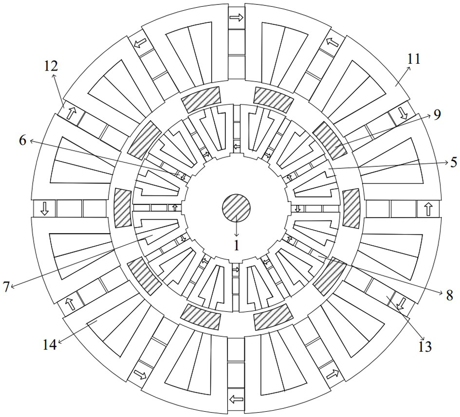
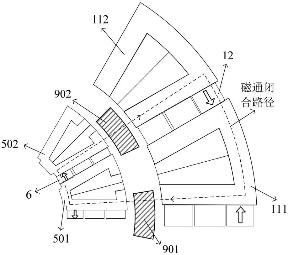
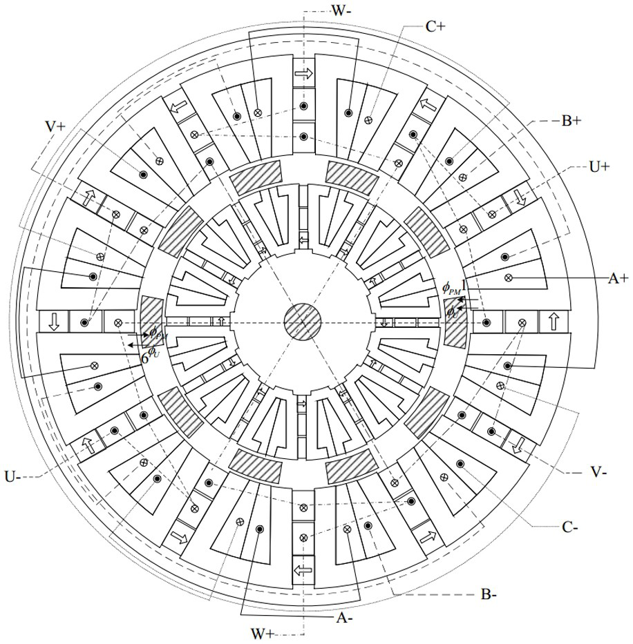
[0026] like Figures 1 to 9 As shown in the figure, a dual-stator bearingless magnetic flux switching motor without rotor iron yoke magnetic circuit coupling of the pre...


PUM


Abstract

The invention relates to a double-stator bearingless magnetic flux switching motor without rotor yoke magnetic circuit coupling, which comprises a rotating shaft, an inner stator, a rotor and an outer stator which are sequentially arranged along the radial direction, and is characterized in that the rotor comprises a rotor bracket and rotor cores which are uniformly arranged along the circumferential direction of the rotor bracket; the rotor core is connected with a rotating shaft through a rotor support to form a motor rotor. The inner stator comprises an inner stator support, the inner stator support is provided with a plurality of inner stator iron cores along the circumference, and high-coercivity permanent magnets which are magnetized alternately in the tangential direction are embedded between the adjacent inner stator iron cores. The outer stator comprises an outer stator support, the outer stator support is provided with a plurality of outer stator iron cores along the circumference, and high-coercivity permanent magnets which are magnetized alternately in the tangential direction are embedded between the adjacent outer stator iron cores. On the premise of not using a magnetic isolation ring, through the rotor magnetic circuit design, the defect of magnetic circuit coupling of the inner stator and the outer stator of the double-stator bearingless magnetic flux switching motor under a complex magnetic circuit is overcome, the size of the rotor is effectively reduced, and the power density and the efficiency of the motor are improved.

Description

Technical field: [0001] The invention relates to a double-stator bearingless magnetic flux switching motor without rotor iron yoke magnetic circuit coupling. Background technique: [0002] The magnetic flux switching permanent magnet motor has the characteristics of simple rotor structure and good heat dissipation effect of the permanent magnet located on the stator, and is used in high-power transmission systems. The bearingless magnetic flux switching motor adds suspension windings on the basis of the original structure, so that the motor has the advantages of a magnetic bearing motor. In order to accurately realize the suspension control of the bearingless flux-switching motor, the bias magnetic field generated by the permanent magnet is often smaller than that of the ordinary flux-switching motor, which greatly reduces the power density of the motor. The double-stator structure can make full use of the internal space of the motor and effectively improve the power densit...

Claims


Application Information

Patent Timeline
Patent Type & Authority Applications(China)
IPC IPC(8): H02K16/04H02K1/30H02K1/17H02K1/18H02K3/12H02K3/28
CPCH02K16/04H02K1/30H02K1/17H02K1/185H02K1/187H02K3/12H02K3/28
Inventor 周扬忠梁彤伟何佳佳钟天云
Owner FUZHOU UNIV
Learn More