
Thermal power plant boiler system and steam turbine power generation system with same

A technology for power generation systems and thermal power plants, which is applied in steam generation, steam engine installations, steam generation installations, etc., can solve the problem of high coupling between boiler waste heat recovery system and boiler and cannot be applied to boiler system, etc., and achieve the effect of low coupling degree.

Pending Publication Date: 2022-07-22
XIAN THERMAL POWER RES INST CO LTD +1
View PDF0 Cites 0 Cited by
  • Summary
  • Abstract
  • Description
  • Claims
  • Application Information

AI Technical Summary

Problems solved by technology

[0004] Therefore, the technical problem to be solved by the present invention is to overcome the defect that the high degree of coupling between the boiler waste heat recovery system and the boiler in the prior art cannot be applied to the operating boiler system, thereby providing a thermal power plant boiler system and Steam turbine power generation system with it

Method used


Image

  • Thermal power plant boiler system and steam turbine power generation system with same

Examples


Embodiment 1

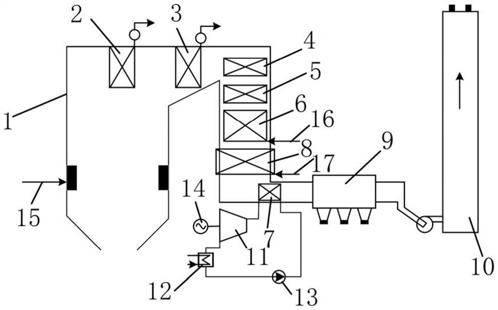
[0030] like figure 1 Shown is a boiler system of a thermal power plant provided in this embodiment, including: a boiler body 1 and a waste heat recovery circulation pipeline for recovering waste heat in high temperature flue gas in the boiler body 1 .

[0031] An evaporator 7 is installed in the tail flue of the boiler body 1. The high temperature flue gas enters the furnace and exchanges heat with the evaporator 7. A pulverized coal inlet 15 is provided on the side wall of the furnace for adding pulverized coal to the boiler body 1 for combustion. A superheater group, a reheater group, an air preheater 8 and a dust collector 9 are also installed in the furnace chamber of the boiler body 1. The evaporator 7 is arranged between the air preheater 8 and the dust collector 9. The air preheater 8 The air inlet 17 is communicated with the upper part. The evaporator 7 is made of corrosion-resistant and wear-resistant materials such as corrosion-resistant low-alloy carbon steel, comp...

Embodiment 2

[0036] This embodiment provides a steam turbine power generation system, including the thermal power plant boiler system described in Embodiment 1. It also includes a high-pressure cylinder, a medium-pressure cylinder and a low-pressure cylinder that are coaxially connected. The steam-side output end of the low-pressure cylinder is sequentially installed with a condenser, a condensate pump, a low-pressure heater, a deaerator, a feed pump and a high-pressure heater. The water output by the boiler is input to the boiler body 1 of the boiler system of the thermal power plant for heating, and then input to the high-pressure cylinder and the medium-pressure cylinder to complete the cycle. The steam-side outlet end of the final-stage superheater 2 is communicated with the high-pressure cylinder, and the steam-side outlet end of the final-stage reheater 3 is communicated with the medium-pressure cylinder.

[0037] A circulating cooling branch is communicated between the condenser and...


PUM


Abstract

The invention relates to the technical field of thermal power generation, in particular to a thermal power plant boiler system and a steam turbine power generation system with the same. The thermal power plant boiler system comprises a boiler body, an evaporator is installed in a tail flue of the boiler body, and high-temperature flue gas enters a hearth and then exchanges heat with the evaporator; the waste heat recovery circulation pipeline comprises the evaporator, an expansion unit, a condenser and a working medium pump which are connected in a circulation mode, and a generator is coaxially installed on the expansion unit. The waste heat recovery circulation pipeline is only connected with the multiple stages of evaporators in the boiler body in series to take heat, the coupling degree is low, when equipment in the waste heat recovery circulation pipeline breaks down and needs to be maintained, the boiler body can still operate normally, a boiler system does not need to be shut down, and normal operation of power generation work cannot be affected. When an existing boiler body is transformed, only the evaporator and the waste heat recovery circulating pipeline need to be additionally arranged, and preheating recycling can be conducted on a boiler system put into production.

Description

technical field [0001] The invention relates to the technical field of thermal power generation, in particular to a boiler system of a thermal power plant and a steam turbine power generation system having the same. Background technique [0002] The heat loss of the boiler mainly includes: exhaust gas loss, gas incomplete combustion heat loss, solid incomplete combustion heat loss, heat dissipation loss and ash physical heat loss. In these heat losses, the vast majority is smoke loss. Exhaust heat loss refers to the heat loss that occurs when the flue gas of the boiler is discharged from the boiler, and part of the heat is taken away by the atmosphere. Generally, the heat loss of the boiler flue gas is in the range of 4% to 8%, which is easily affected by the container for flue gas extraction and the temperature during flue gas extraction. Generally, in order to prevent the tail of the boiler from being corroded by low temperature, the temperature of the exhaust gas is con...

Claims


Application Information

Patent Timeline
IPC IPC(8): F22B33/18F22D1/00F22G3/00F23L15/00F23J15/02F01K11/00F01D15/10
CPCF22B33/18F22D1/00F22G3/00F23L15/00F23J15/022F01K11/00F01D15/10
Inventor 薛朝囡许朋江居文平邵林芳段周朝曹志华张建元邓佳
Owner XIAN THERMAL POWER RES INST CO LTD
Learn More