Printed circuit board (PCB) ink printing device
A technology of ink printing and dust removal device, which is applied in printing, printing presses, rotary printing presses, etc., can solve the problems of low printing force, ink is not easy to adhere, and work quality is poor, so as to improve printing quality, increase printing intensity, and improve The effect of work efficiency
- Summary
- Abstract
- Description
- Claims
- Application Information
AI Technical Summary
Problems solved by technology
Method used
Image
Examples
Embodiment 1
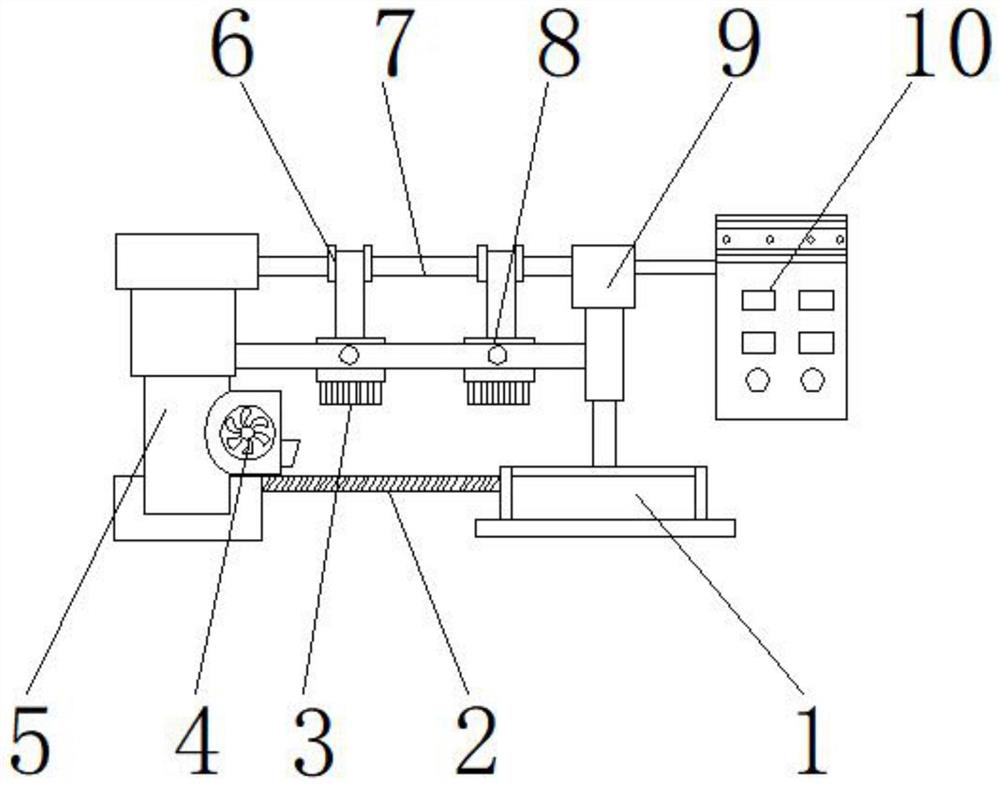
[0027] like Figure 1-5 As shown, the present invention provides a PCB ink printing device, comprising a main body 1, a bracket 9 is arranged on the upper end of the main body 1 of the main body 1, a control box 10 is arranged on one side of the bracket 9, and a placing table is arranged on one side of the main body 1 Plate 2, the upper end of the placing platen 2 is provided with a dust removal device 4, one side of the dust removal device 4 is provided with a column 5, a printing head 3 is arranged above the placing platen 2, and a pressure device 8 is arranged on the upper end of the printing head 3, A suspension sliding device 6 is arranged above the pressurizing device 8, the beam 7 traverses the interior of the suspension sliding device 6 and the two ends are respectively connected with the column 5 and the bracket 9; the dust removal device 4 includes a fan 41, a dust collector 42, a blower Dust cleaning device 43 , air collecting hood 44 , air intake duct 45 , dust col...
Embodiment 2
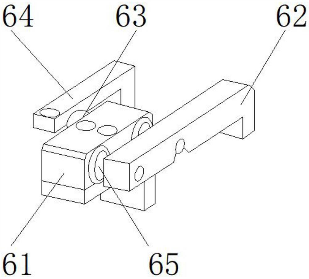
[0030] like Figure 1-5As shown, on the basis of Embodiment 1, the present invention provides a technical solution: preferably, the suspension sliding device 6 includes a mounting block 61, a No. 1 L-shaped sliding rod 62, a locking hole 63, and a No. 2 L-shaped sliding rod 64 , the movable slot 65, the movable slot 65 is located on both sides of the installation block 61, the lock hole 63 is located at the upper end of the installation block 61, the No. On the other side of the slot 65, a movable slot 65 is provided between the installation block 61 and the No. 1 L-shaped sliding rod 62, and one side of the No. 1 L-shaped sliding rod 62 is movably connected to one side of the installation block 61 through the movable groove 65, A welding block is provided between the locking hole 63 and the mounting block 61 , and the lower end of the locking hole 63 is fixedly connected to the upper end of the mounting block 61 through the welding block.
[0031] In this embodiment, the pri...
Embodiment 3
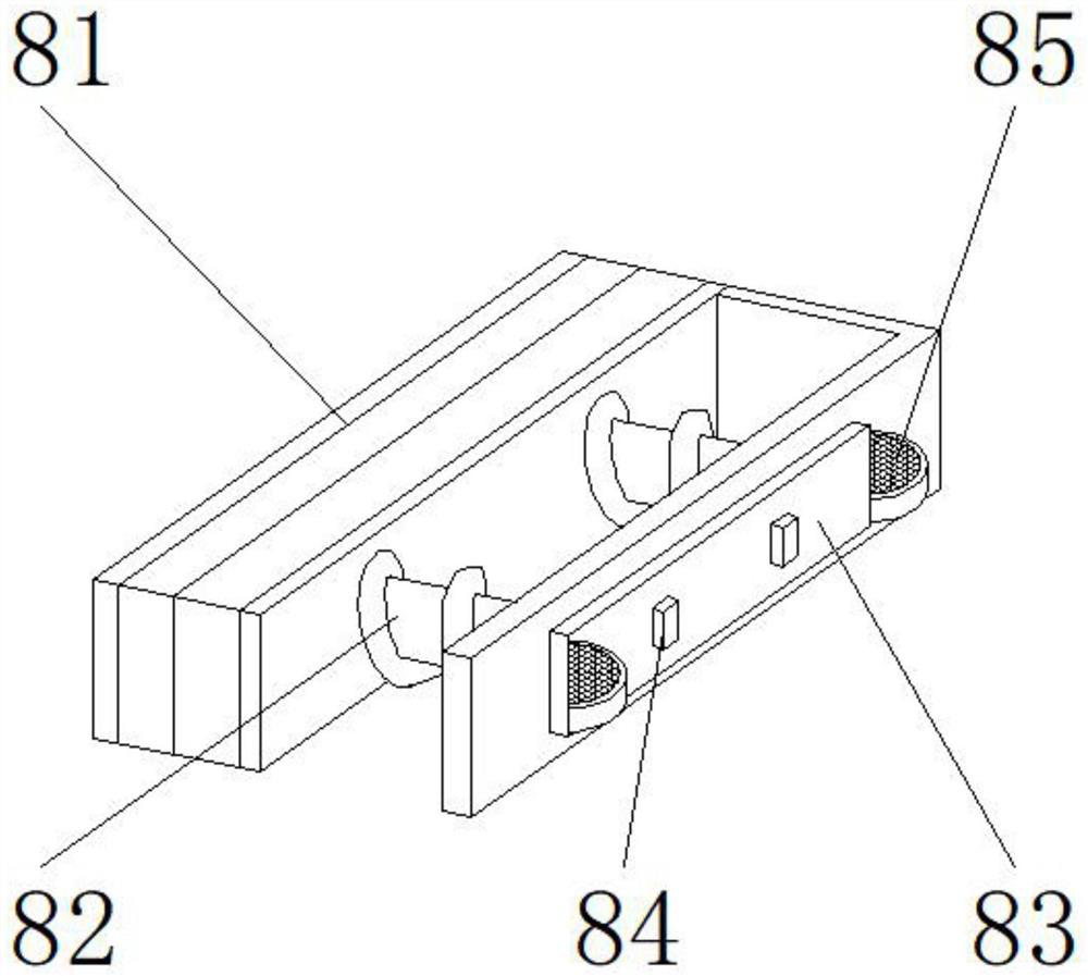
[0033] like Figure 1-5 As shown, on the basis of Embodiment 1, the present invention provides a technical solution: preferably, the pressing device 8 includes a driving device 81, a screw shaft 82, a backing plate 83, a pressing block 84, a cam 85, and a screw shaft 82 It is located on one side of the driving device 81, the backing plate 83 is located on one side of the screw shaft 82, the pressure block 84 is located on one side of the backing plate 83, the cam 85 is located at both ends of the backing plate 83, the backing plate 83 and the pressing block 84 A welding block is arranged between the two sides, one side of the pressing block 84 is fixedly connected to one side of the backing plate 83 through the welding block, one side of the screw shaft 82 is rotatably connected to one side of the driving device 81, and the space between the cam 85 and the backing plate 83 A card slot is provided, and one side of the cam 85 is detachably connected to one side of the backing pl...
PUM
 Abstract
Description
Claims
Application Information
 - R&D
- Intellectual Property
- Life Sciences
- Materials
- Tech Scout
- Unparalleled Data Quality
- Higher Quality Content
- 60% Fewer Hallucinations
Browse by: Latest US Patents, China's latest patents, Technical Efficacy Thesaurus, Application Domain, Technology Topic, Popular Technical Reports.
© 2025 PatSnap. All rights reserved.Legal|Privacy policy|Modern Slavery Act Transparency Statement|Sitemap|About US| Contact US: help@patsnap.com


