
Fuel cell system and air humidity adjusting method thereof

A fuel cell system and air humidity technology, applied in fuel cells, electrical components, circuits, etc., to achieve the effects of improving service life, ensuring stable operation, and reducing volume

Pending Publication Date: 2022-07-12
佛山仙湖实验室 +2
View PDF12 Cites 0 Cited by
  • Summary
  • Abstract
  • Description
  • Claims
  • Application Information

AI Technical Summary

Problems solved by technology

[0003] The present invention provides a fuel cell system and its air humidity adjustment method to solve one or more technical problems existing in the prior art, and at least provide a beneficial option or create conditions

Method used


Image

  • Fuel cell system and air humidity adjusting method thereof
  • Fuel cell system and air humidity adjusting method thereof

Examples


Embodiment Construction

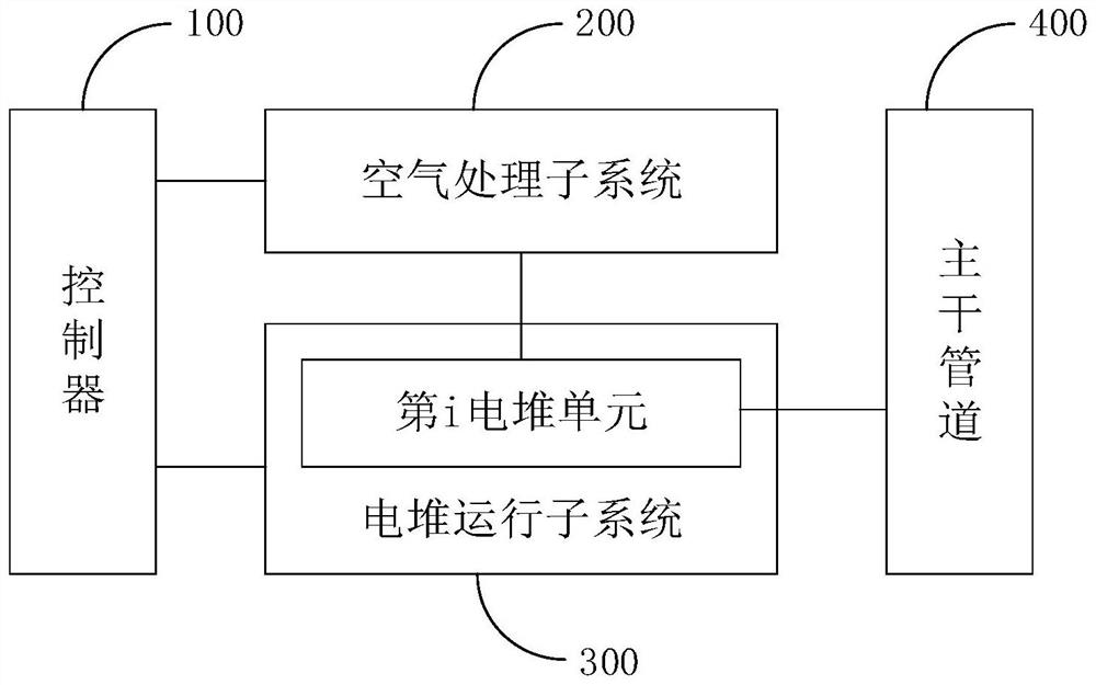
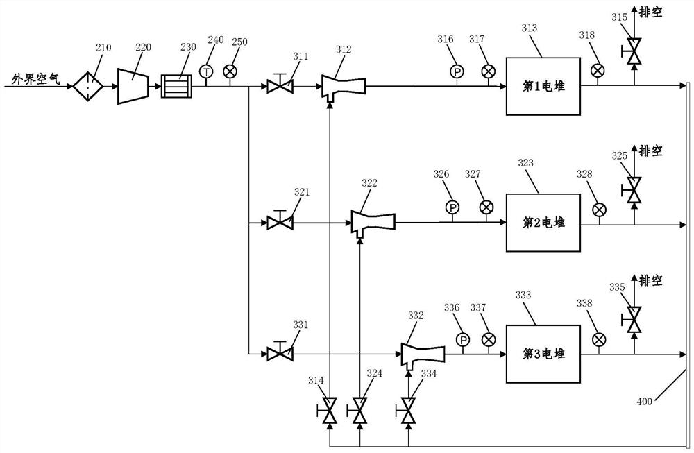
[0031] In order to make the objectives, technical solutions and advantages of the present invention clearer, the present invention will be further described in detail below with reference to the accompanying drawings and embodiments. It should be understood that the specific embodiments described herein are only used to explain the present invention, but not to limit the present invention.

[0032] It should be noted that although the functional modules are divided in the schematic diagram of the system and the logical sequence is shown in the flow chart, in some cases, the modules may be divided differently from the system or executed in the order in the flow chart. steps shown or described. The terms "first", "second" and the like in the description and claims and the above drawings are used to distinguish similar objects and are not necessarily used to describe a specific order or sequence.

[0033] Please refer to Figure 1 to Figure 2 , an embodiment of the present inve...


PUM


Abstract

The invention discloses a fuel cell system and an air humidity adjusting method thereof.The system comprises a main pipeline, a controller, an air processing subsystem and an electric pile operation subsystem, the air processing subsystem and the electric pile operation subsystem are connected with the controller, the electric pile operation subsystem comprises a plurality of electric pile units, and each electric pile unit comprises an inlet valve, an ejector, an electric pile and an outlet valve; the air treatment subsystem is connected with a primary inflow port of the ejector through an inlet valve, an outlet of the ejector is connected with an air inlet of the electric pile, an exhaust port of the electric pile is connected with the input end of the main pipeline, and the output end of the main pipeline is connected with a secondary inflow port of the ejector through an outlet valve. And the ejector is used for fully mixing dry air provided by the air treatment subsystem and wet air provided by the main pipeline so as to adjust the humidity of air entering the electric pile. According to the invention, the ejector is adopted to replace a traditional membrane humidifier, so that the production cost is reduced; and through mutual adjustment among the multiple electric pile units, the service life of the multiple electric piles in the system is prolonged, so that the economic loss is reduced.

Description

technical field [0001] The invention relates to the technical field of fuel cell applications, in particular to a fuel cell system and an air humidity adjustment method thereof. Background technique [0002] When the fuel cell system is working, the air entering the stack inside the system needs to have a certain humidity requirement. The existing fuel cell system mainly improves the air humidity entering the stack by arranging a membrane humidifier at the inlet of the stack, but the membrane humidifier has the disadvantages of large volume and high price; in addition, the existing fuel cell system often Set up a single stack, when there is insufficient air humidity inside the stack, if the water content inside the stack is increased by forcibly increasing the operating power of the stack, the air humidity inside the stack can be increased, but it may be It will lead to the damage of the stack and cause irreversible economic losses; if the air humidity inside the stack cann...

Claims


Application Information

Patent Timeline
Patent Type & Authority Applications(China)
IPC IPC(8): H01M8/04089H01M8/04119H01M8/04492
CPCH01M8/04089H01M8/04126H01M8/04492Y02E60/50
Inventor 刘若璐吴焯峰孟子寒龚聪文张锐明
Owner 佛山仙湖实验室
Learn More