
Heavy-load thrust bearing with multiple cooling circulation functions

A cooling cycle, thrust bearing technology, applied in the direction of rotating bearings, bearings, shafts and bearings, etc., can solve the problems of increasing the complexity of bearings, affecting the reliability of bearings, limiting the bearing capacity of bearings, etc., to improve reliability and reliability. Effectiveness of service life, long operating life, improved stability and load-carrying capacity

Pending Publication Date: 2022-07-12
SHAANXI UNIV OF SCI & TECH
View PDF0 Cites 0 Cited by
  • Summary
  • Abstract
  • Description
  • Claims
  • Application Information

AI Technical Summary

Problems solved by technology

With the development of rotating machinery towards high-speed and high-pressure ratio working conditions, the problem of overheating in thrust bearings has become prominent. Due to material and space constraints, the stable operation of thrust bearings in extreme working conditions has become one of the main factors limiting the development of units.
At present, the world's leading bearing companies have carried out a series of innovations in bearing tile surface materials, tile body materials, and oil inlet methods, and developed various new types of bearings, such as advanced LEG bearings, but only focus on ensuring the thermal conductivity of materials , high temperature resistance and sufficient oil flow, and in terms of heat dissipation of the bearing, only the improvement of the material limits the improvement of the bearing capacity; on the other hand, the heat dissipation design of the bearing increases the complexity of the bearing and reduces the bearing capacity. It affects the strength of the bearing body and affects the reliability of the entire bearing

Method used


Image

  • Heavy-load thrust bearing with multiple cooling circulation functions
  • Heavy-load thrust bearing with multiple cooling circulation functions
  • Heavy-load thrust bearing with multiple cooling circulation functions

Examples


Embodiment Construction

[0035] The technical solutions in the embodiments of the present invention will be clearly and completely described below with reference to the accompanying drawings in the embodiments of the present invention.

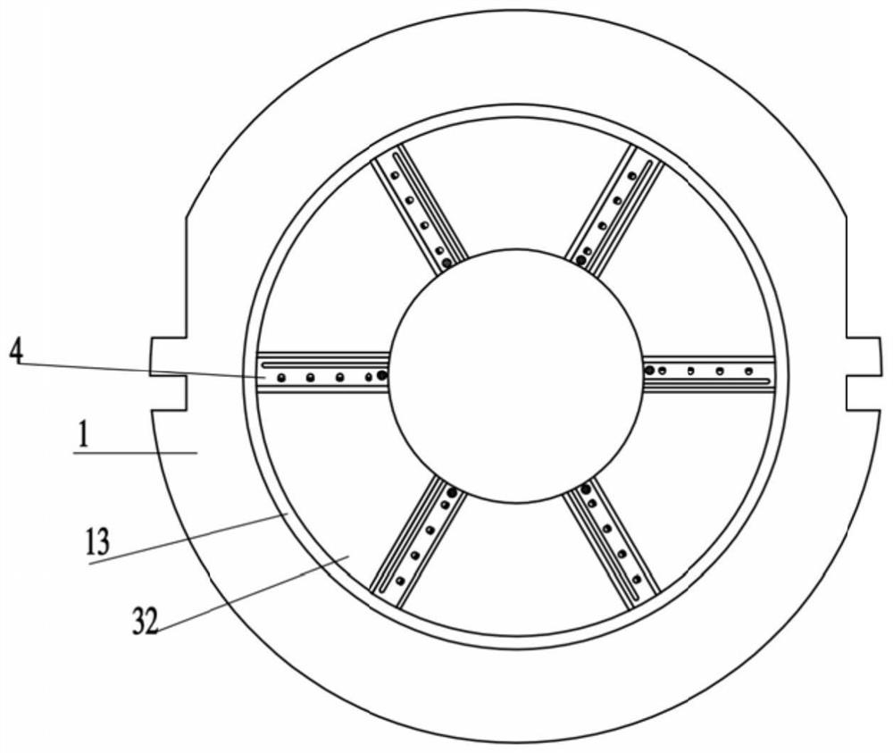
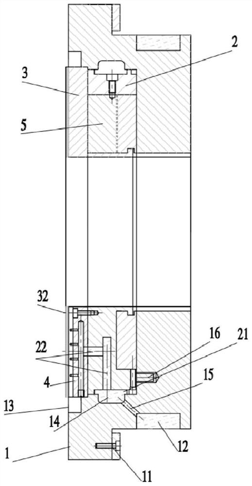
[0036] like figure 1 and figure 2 As shown, this embodiment provides a heavy-duty thrust bearing with multiple cooling cycle functions, including a bearing body 1 , a thrust ring 2 , a thrust block group 3 , an oil injection mechanism 4 , and a balance block group 5 .

[0037]The outer side of the bearing body 1 is provided with an oil inlet ring groove 12, the inner cavity of the bearing body 1 is matched with the thrust ring 2 and the thrust block group 3, and the inner cavity is matched with the thrust block group 3 in the axial direction. There is an external cooling oil groove 13 of the thrust block group 3, an oil inlet ring groove 2 21 is provided on the outer periphery of the thrust ring 2, and an internal cooling oil is provided at the matching position bet...


PUM


Abstract

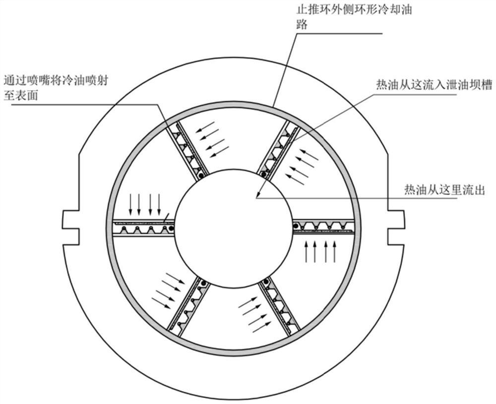
The invention discloses a heavy-load thrust bearing with multiple cooling circulation functions. The heavy-load thrust bearing comprises a bearing body, a thrust ring, a thrust block group, an oil injection mechanism and a balance block group, an oil inlet ring groove is designed outside the bearing body, an inner cavity of the bearing body is matched with the thrust ring and the tile group, and an annular cooling oil groove is designed at the axial matching part of the inner cavity of the bearing body and the tile and is used for collecting cold oil on the outer circle of the thrust block so as to cool the tile body; the oil injection structure and the thrust ring are positioned through a profiled groove, an oil injection nozzle with an inclination angle in the rotating direction is arranged in the middle of the top of the oil injection mechanism, the inclination angle ranges from 45 degrees to 80 degrees, a hot oil drainage dam groove is formed in the position, on the oil outlet side of the tile, of the top of the oil injection mechanism, and multiple cooling oil channels and an optimized oil supply system are provided. The thrust bearing can effectively solve the problem of overtemperature of the existing thrust bearing under the conditions of high speed and large load, and the reliability and the service life of the bearing under the high working condition are improved and prolonged.

Description

technical field [0001] The invention belongs to the field of machinery and relates to a thrust bearing, in particular to a heavy-duty thrust bearing with multiple cooling cycle functions. Background technique [0002] Thrust bearing is a key component to ensure the axial position of the rotor and bear the axial thrust of the rotor. It is widely used in various rotating machinery such as blowers, compressors, steam turbines, and gas turbines. With the development of rotating machinery towards high-speed and high-pressure ratio conditions, the over-temperature problem of thrust bearings has become prominent. Due to material and space constraints, the stable operation of thrust bearings under extreme conditions has become one of the main factors limiting the development of the unit. At present, the world's leading bearing companies have carried out a series of innovations in bearing surface materials, body materials, oil inlet methods, etc., and developed various new types of b...

Claims


Application Information

Patent Timeline
IPC IPC(8): F16C17/08F16C33/04F16C33/02F16C37/00
CPCF16C17/08F16C33/04F16C33/02F16C37/00F16C2360/43F16C2360/23F16C2360/22Y02E10/20
Inventor 杨培基庞凯赵志明
Owner SHAANXI UNIV OF SCI & TECH
Learn More