
Composite magnetism gathering type permanent magnet-superconducting coupling transmission device for cryopump

A technology of transmission device and cryopump, which is applied in the field of composite magnetism-concentrating permanent magnet-superconducting coupling transmission device for cryopumps, which can solve the problem of difficulty in meeting the technical requirements of cryogenic liquid pumps, limited space for transmission torque improvement, and the difficulty of permanent magnet materials. It can eliminate the problem of low-temperature rotary dynamic sealing, improve torque transmission performance, and stabilize non-contact transmission.

Pending Publication Date: 2022-07-05
HENAN POLYTECHNIC UNIV
View PDF1 Cites 2 Cited by
  • Summary
  • Abstract
  • Description
  • Claims
  • Application Information

AI Technical Summary

Problems solved by technology

[0004] However, affected by the low temperature environment, the fragility of the permanent magnet material of the conventional magnetic coupler increases, and the mechanical strength decreases. When the copper material generates electromagnetic torque, it also generates a large eddy current loss, resulting in the vaporization of the low temperature liquid.
In addition, the main and driven sides of the magnetic coupling are separated by the container wall, the working air gap is large, and the space for improving the transmission torque is limited
From the perspective of extremely low temperature environment and large air gap working conditions, the above-mentioned magnetic coupling transmission device is difficult to meet the technical requirements of cryogenic liquid pump applications

Method used


Image

  • Composite magnetism gathering type permanent magnet-superconducting coupling transmission device for cryopump
  • Composite magnetism gathering type permanent magnet-superconducting coupling transmission device for cryopump
  • Composite magnetism gathering type permanent magnet-superconducting coupling transmission device for cryopump

Examples


Embodiment 1

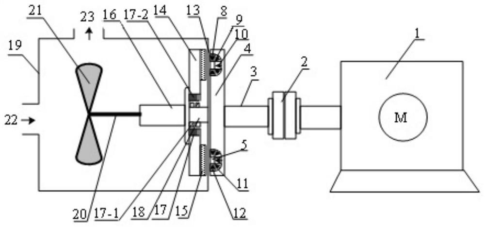
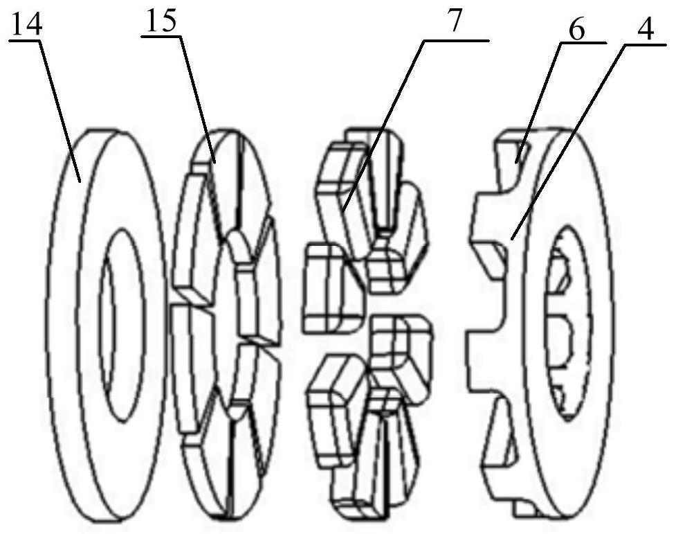
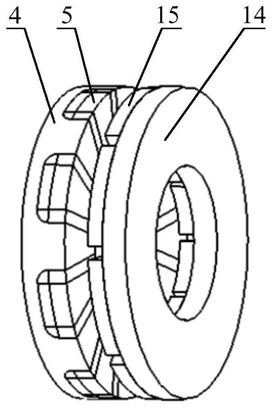
[0031] like Figure 1-3 As shown, a composite magnetic concentrating permanent magnet-superconducting coupling transmission device for a cryopump comprises a motor 1, a coupling 2 and a cryopump, the cryopump comprising a pump casing 19 and a blade arranged inside the pump casing 19 The axle 20 and the impeller 21, the pump inlet 22 and the pump outlet 23 are provided on the pump casing 19, and the cryopump also includes an input shaft 3 and a permanent magnet rotor yoke 4 arranged on the outside of the pump casing 19 at the drive end of the cryopump, And the superconducting rotor yoke 14 and the output shaft 16 arranged on the inner side of the pump casing 19 at the driving end of the cryopump; the motor 1 is connected with the input shaft 3 of the cryopump through the coupling 2, and the input shaft 3 is fixed coaxially There is a permanent magnet rotor yoke 4; the inner side of the permanent magnet rotor yoke 4 is provided with a plurality of U-shaped grooves 6 along the ci...

Embodiment 2

[0037] like Figure 6-7 As shown in the figure, the difference between this embodiment and Embodiment 1 is only that: the composite magnetism-converging U-shaped permanent magnet pole 7 is composed of the sixth permanent magnet 24, the seventh permanent magnet 25 and the eighth permanent magnet 26 in sequence in a U-shaped cross-section. It is formed by closely fitting and splicing, wherein the cross section of the seventh permanent magnet 25 is semicircular, and the magnetization direction of each permanent magnet is directed to the guide magnet piece 5 .

[0038] like Figure 8 As shown, the axial magnetic flux density of the two-dimensional expansion model at the air gap of 1mm under the same amount of permanent magnet material with different combinations of magnetic poles, where Halbach and concentrating magnetic poles respectively represent the Halbach magnetic poles in the prior art The U-shaped magnetic pole represents the composite magnetic-focusing U-shaped permanent...


PUM


Abstract

The invention belongs to the field of magnetic coupling transmission in low-temperature engineering, and particularly relates to a composite magnetism gathering type permanent magnet-superconducting coupling transmission device for a low-temperature pump, the low-temperature pump comprises a pump shell, an impeller shaft, an impeller, an input shaft, a permanent magnet rotor yoke, a superconducting rotor yoke and an output shaft, the input shaft and the permanent magnet rotor yoke are arranged on the outer side of the pump shell, and the superconducting rotor yoke and the output shaft are arranged on the inner side of the pump shell; the inner side of the permanent magnet rotor yoke is provided with a plurality of U-shaped grooves internally provided with composite magnetism gathering type U-shaped permanent magnet poles and magnetic conductive iron sheets, a circle of fan-shaped superconducting sheets are arranged on the superconducting rotor yoke at intervals, the permanent magnet poles and the superconducting sheets are correspondingly connected in a non-contact mode at intervals through working air gaps, and the middle of the superconducting rotor yoke is rotationally connected with a suspension component through a radial magnetic suspension bearing. The outer side of the superconducting rotor yoke is fixedly connected with the output shaft. By improving the arrangement mode of the magnetic poles of the permanent magnet disc, leakage flux of the permanent magnet rotor is reduced, and excitation magnetic field distribution is improved; the transmission torque is improved by using the strong capture magnetic field and high current-carrying density of the superconducting sheet, and non-contact torque transmission from a normal temperature end to a low temperature end is realized.

Description

technical field [0001] The invention belongs to the field of magnetic coupling transmission in cryogenic engineering, and in particular relates to a composite magnetic concentrating permanent magnet-superconducting coupling transmission device for a cryogenic pump. Background technique [0002] The production and transportation of cryogenic liquids such as cryogenic clean energy and cryogenic propellants for aerospace vehicles are mostly completed by cryogenic pumping devices. At present, small and medium-sized cryogenic liquid pumps mostly adopt a pump-machine-separated structure coupled with a long shaft. Due to the huge temperature difference between the two ends of the pump connected by the long shaft, this type of pumping device has the problems of difficulty in sealing and frequent failures. [0003] With the development of permanent magnet materials, magnetic drive technology has been proposed and used in various mechanical equipment such as fans and pumps. The magne...

Claims


Application Information

Patent Timeline
IPC IPC(8): H02K49/10H02K1/2795H02K7/09F16C32/04
CPCH02K49/108H02K1/2793H02K7/09F16C32/0408F16C32/0438Y02E40/60
Inventor 艾立旺苗森许孝卓肖磊
Owner HENAN POLYTECHNIC UNIV
Learn More