2K line-scan digital camera and automatic phase alignment method

A camera and K-line technology, applied in the field of lithography machines, can solve the problems of increasing software versions, difficult to guarantee the synchronization delay of focusing and leveling points, etc., to reduce the timing phase difference, realize the automatic phase calibration function, reduce the The effect of cable differences

Pending Publication Date: 2022-07-01
SHANGHAI MICRO ELECTRONICS EQUIP (GRP) CO LTD
View PDF5 Cites 0 Cited by
  • Summary
  • Abstract
  • Description
  • Claims
  • Application Information

AI Technical Summary

Problems solved by technology

And when the number of cameras that need to collect images increases, that is, when the leveling and focusing points increase, due to the limitation of interfaces and computing power, the number of required boards increases, and the software version will also increase accordingly.
Moreover, in the existing focusing and leveling system, limited by the interface of the image acquisition card, the image data transmission rate and processing rate are determined by the slowest board among the image acquisition board and the multi-point fitting board.
It can be understood that when there are many focusing and leveling points required, it is easy to introduce a phase difference in the timing due to cable differences during the signal transmission process through the cable, making it difficult to obtain the synchronization delay of each focusing and leveling point Assure

Method used


Image

  • 2K line-scan digital camera and automatic phase alignment method
  • 2K line-scan digital camera and automatic phase alignment method
  • 2K line-scan digital camera and automatic phase alignment method

Examples


Embodiment Construction

[0066] The present invention will be further described in detail below in conjunction with the accompanying drawings and embodiments. It should be understood that the specific embodiments described herein are only used to explain the present invention, but not to limit the present invention. In addition, it should be noted that, for the convenience of description, the drawings only show some but not all structures related to the present invention.

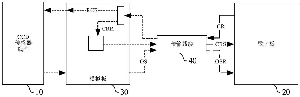
[0067] figure 2 It is a schematic structural diagram of a 2K line scan camera provided by an embodiment of the present invention, refer to figure 2 , the 2K line scan camera includes a CCD sensor line array 10, a digital board 20, an analog board 30 and a transmission cable 40. The digital board 20 is electrically connected to the analog board 30 through the transmission cable 40, and the analog board 30 is connected to the CCD sensor line array 10. electrical connection;

[0068] The digital board 20 is used to send the regis...


PUM


Abstract

The embodiment of the invention discloses a 2K line-scan digital camera and an automatic phase alignment method. The 2K linear array camera comprises a CCD sensor linear array, a digital board, an analog board and a transmission cable, and the digital board is used for calculating the transmission phase difference between an output clock return signal CRS and a register output clock CR and compensating the transmission phase difference into the phase difference between an output signal return signal OSR and the register output clock CR. According to the embodiment of the invention, the phase automatic calibration function can be realized, the phase deviation of the time sequence phase of the camera register output clock and the camera output signal caused by external interference, self-aging and the like of a transmission cable is dynamically reduced, and the output signal return signal OSR and the register output clock CR are ensured to have nearly the same phase. And the influence of cable difference on the accuracy of the image pixel gray scale is reduced.

Description

technical field [0001] Embodiments of the present invention relate to the technical field of lithography machines, and in particular, to a 2K line scan camera and an automatic phase contrast method. Background technique [0002] A projection lithography machine is a device that projects a mask pattern onto the surface of a silicon wafer through a projection objective lens. During the exposure process of the lithography machine, if the silicon wafer is out of focus or tilted relative to the focal plane of the objective lens, some areas in the exposure field of view will be outside the effective focal depth, which will seriously affect the quality of lithography. Therefore, focus adjustment must be used. Leveling system for precise control. [0003] figure 1 It is the control logic diagram of the existing lithography machine focusing and leveling system, refer to figure 1 , In the common control logic of focusing and leveling, multiple cameras are used to collect multiple s...

Claims


Application Information

Patent Timeline
Patent Type & Authority Applications(China)
IPC IPC(8): H04N5/232G03F7/20
CPCG03F7/20H04N23/60
Inventor 陈钰思阳杨宣华
Owner SHANGHAI MICRO ELECTRONICS EQUIP (GRP) CO LTD
Why Eureka
Try Eureka