A Laser Array Coupling System with Beam Correction

A laser array and coupling system technology, applied in the field of laser array coupling systems, can solve the problems of residual divergence angle, space waste, large spot size, etc., and achieve the effects of eliminating residual divergence angle, reducing complexity and increasing power

Active Publication Date: 2022-08-09
江苏镭创高科光电科技有限公司
View PDF12 Cites 0 Cited by
  • Summary
  • Abstract
  • Description
  • Claims
  • Application Information

AI Technical Summary

Problems solved by technology

[0004] The prior art provides a technical solution in which TO-Can packaged semiconductor lasers are installed in both horizontal and vertical directions. The emitted light is not beam corrected, and there is a significant residual divergence angle, resulting in an excessively large spot size when coupled into the fiber, making it difficult to fully couple into a thinner fiber (such as a 100um core)
[0005] The prior art also provides a technical solution in which multiple TO-Can packaged semiconductor lasers are fixed on the heat sink in a ring arrangement. This arrangement causes the output beams to fail to fill the central part of the ring, and the central part is not fully utilized. , resulting in a waste of space

Method used


Image

  • A Laser Array Coupling System with Beam Correction
  • A Laser Array Coupling System with Beam Correction
  • A Laser Array Coupling System with Beam Correction

Examples


Embodiment 1

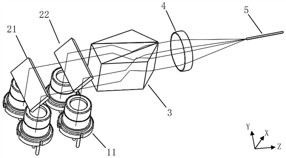
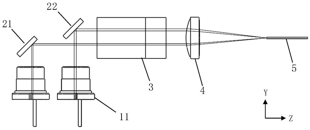
[0055] like Figure 1-3 As shown, this embodiment discloses a laser array coupling system with beam correction, the laser array coupling system with beam correction includes a laser light source, a fast axis adjustment unit, a beam correction composite prism 3, a convergence unit 4 and a single core Fiber 5.

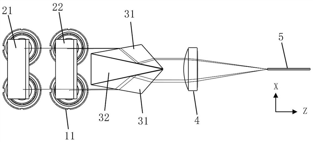
[0056] The laser light source is used for emitting a laser beam array, and the laser light source includes a first group of laser diodes and a second group of laser diodes; wherein the first group of laser diodes and the second group of laser diodes each include at least two laser diodes 11 . refer to image 3 , in this embodiment, both the first group of laser diodes and the second group of laser diodes include two laser diodes 11 , the upper two laser diodes 11 constitute the first group of laser diodes, and the lower two laser diodes 11 constitute the second group of laser diodes diode.

[0057] refer to Figure 4 , the collimated beam output by the laser diode 11...

Embodiment 2

[0066] like Figure 7-8 As shown, the difference between the laser array coupling system with beam correction in this embodiment and the first embodiment is that the transmission direction of the laser beams emitted by the two adjacent laser diodes 11 (above) in the X direction is the Z direction, and the X direction is the same as the one in the X direction. The transmission direction of the laser beams emitted by the adjacent two laser diodes 11 (below) is the Y direction. The fast axis adjustment unit 2 in this embodiment includes a third mirror 23, which is used to phase the X direction. The laser beams emitted by the two adjacent laser diodes 11 (below) are reflected to the beam correction composite prism 3, and the laser beams emitted by the two adjacent laser diodes 11 (above) in the X direction are directly incident on the beam correction composite prism 3, refer to Figure 7 , which also reduces the spacing between adjacent laser beams in the fast axis direction.

Embodiment 3

[0068] like Figure 9-10 As shown, the difference between the laser array coupling system with beam correction in this embodiment and the first embodiment is that the transmission directions of the laser beams emitted by the four laser diodes are all in the Z direction, and the fast axis adjustment unit 2 in this embodiment includes A parallelogram reflecting prism 24, the third reflecting mirror 23 is used to reflect twice the laser beams emitted by the two laser diodes 11 (below) adjacent in the X direction, and then incident on the beam correction composite prism 3, adjacent in the X direction The laser beams emitted by the two laser diodes 11 (above) are directly incident on the beam correction composite prism 3, refer to Figure 9 , which also reduces the spacing between adjacent laser beams in the fast axis direction.


PUM


Abstract

The invention discloses a laser array coupling system with beam correction, comprising: a laser light source for emitting a laser beam array; a fast axis adjustment unit, the fast axis adjustment unit is used to reduce the distance between adjacent laser beams in the fast axis direction ; Beam correction compound prism, including two obtuse-angled triangular prisms with the same structure and symmetrically arranged, used to increase the width of the laser beam in the direction of the slow axis and reduce the distance between adjacent laser beams in the direction of the slow axis; Converging unit and single core The optical fiber, the converging unit is used for coupling the laser beams exiting from the rear refracting surfaces of the two obtuse-angled triangular prisms to the single-core optical fiber. The invention can increase the width of the laser beam in the direction of the slow axis, and simultaneously reduce the spacing of the laser beam in the direction of the fast axis and the slow axis, the laser beam emitted from the beam compound correction prism is compactly arranged, the residual divergence angle is eliminated, and the convergence The resulting smaller spot size allows coupling into smaller diameter single-core fibers. The invention has compact structure and high integration.

Description

technical field [0001] The invention relates to the technical field of semiconductor laser light sources, in particular to a laser array coupling system with beam correction. Background technique [0002] The output beam of the laser diode has an elliptical energy distribution and has astigmatism. Generally, after the vertical direction is collimated, there is still a residual divergence angle in the horizontal direction. It makes it difficult for the coupled light spot to enter the thinner fiber, which affects the coupling efficiency and the optical power output by the fiber. [0003] In order to improve the output optical power, it is generally necessary to use multiple laser diodes for fiber coupling. Due to the limitation of physical size and installation size, the output beams of laser diodes are spaced apart from each other, while the converging lens has physical aperture limitations, which affects the number of received beams and the spot size. Size is limited. Also...

Claims


Application Information

Patent Timeline
Patent Type & Authority Patents(China)
IPC IPC(8): H01S5/40H01S5/00G02B6/42
CPCH01S5/4075H01S5/4012H01S5/0085G02B6/4296
Inventor 程波涛高文宏郭泽彬
Owner 江苏镭创高科光电科技有限公司
Why Eureka
Try Eureka