Dual-mode double-ridge dielectric filled filter
A medium filling and filter technology, which is applied to waveguide-type devices, circuits, electrical components, etc., can solve the problems of filter processing and tuning difficulties, and the filter structure cannot maintain a linear structure, so as to achieve miniaturization and selectivity. The effect of height and volume reduction
- Summary
- Abstract
- Description
- Claims
- Application Information
AI Technical Summary
Problems solved by technology
Method used
Image
Examples
Embodiment 1
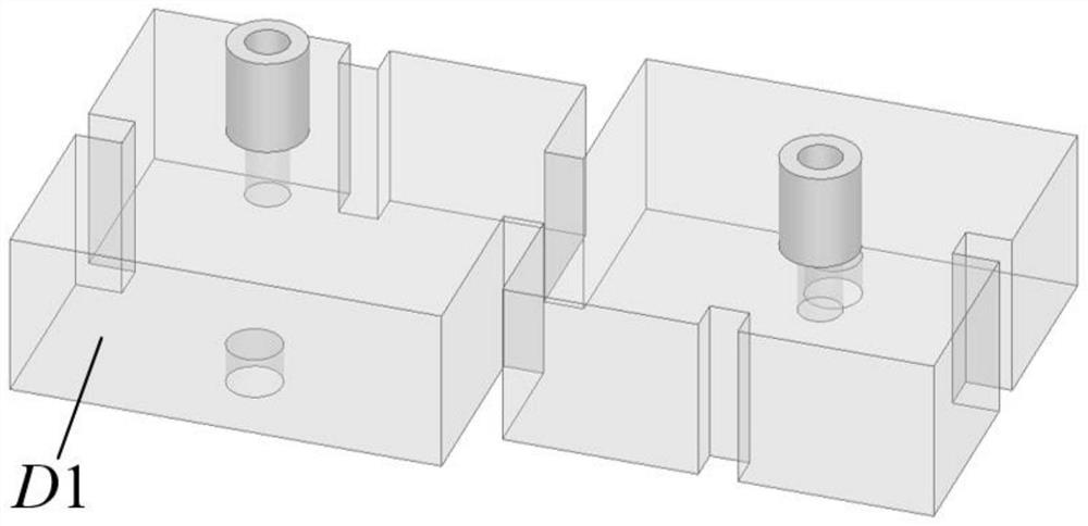
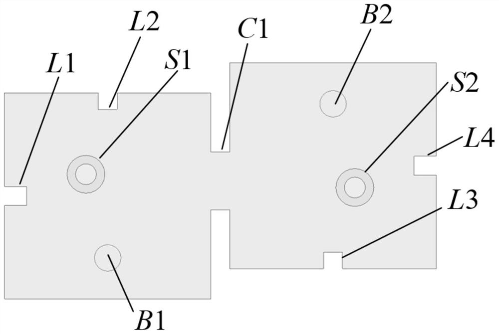
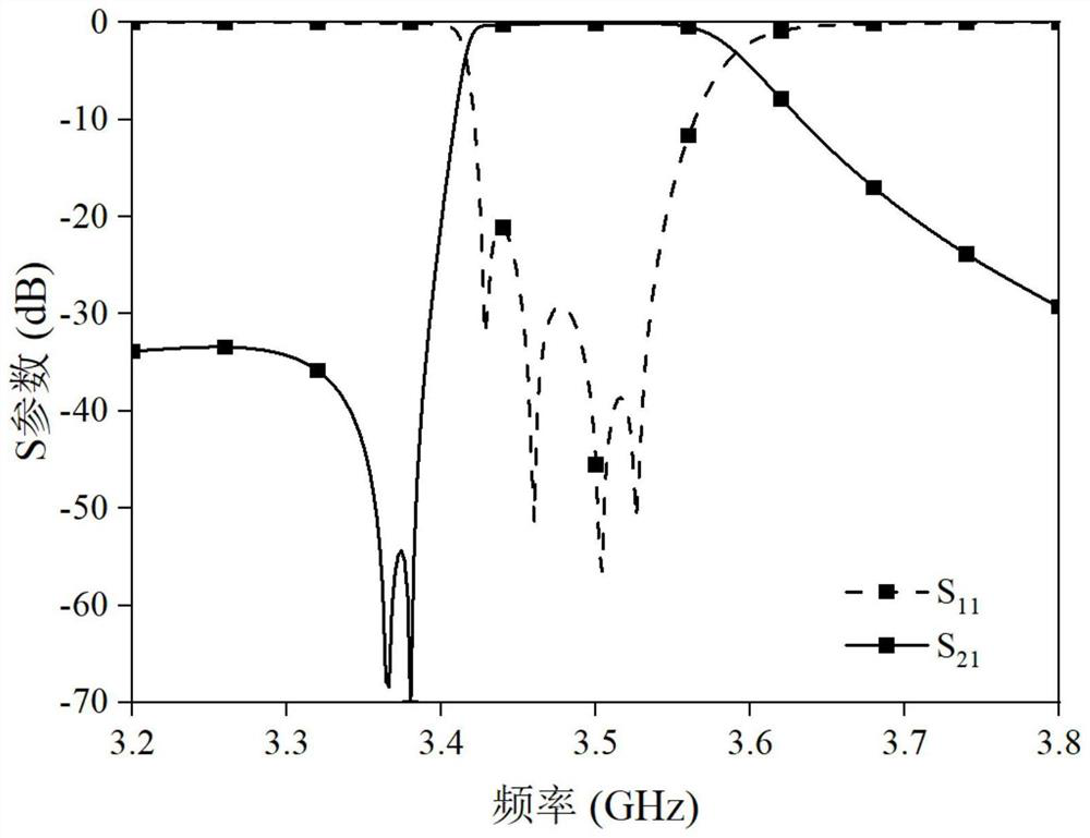
[0025] see figure 1 and figure 2 As shown in the figure, this embodiment provides a dual-mode dual-ridge dielectric-filled filter with asymmetric response, which is a rectangular dielectric block D1 plated with silver on the surface. The top of the dielectric block D1 is connected to the coaxial connectors S1 and S2, and the coaxial connection The filter acts as an input and output port to feed the filter, and the embedded depth of its coaxial inner conductor determines the coupling strength of the input and output ports. Dielectric block D1 is formed with two dual-mode dual-ridge resonators, each of which provides two transmission poles and one transmission zero; where the TE of the dual-mode dual-ridge resonator on the left in the figure 102 Die and TE 201 The resonant frequency of the mode is controlled by the length of the ridge L2 and the length of the ridge L1, respectively, and the ridge L2 and the ridge L1 are loaded orthogonally on the adjacent two sides of the dua...
Embodiment 2
[0028] see Figure 4 As shown, this embodiment provides another dual-mode dual-ridge dielectric filling filter with asymmetric response. Different from Embodiment 1, blind holes are not introduced in this embodiment. Therefore, the TE of the two dual-mode dual-ridge resonators 102 Die and TE 201 The resonant frequency of the mode is controlled only by the length of the ridge.
[0029] Figure 5 The S-parameter curve of the above-mentioned dual-mode dual-ridge dielectric filling filter of this embodiment is shown. It can be seen from the figure that this embodiment can obtain asymmetrical response complementary to that of Embodiment 1, and the two transmission zeros are on the right side of the passband. side.
Embodiment 3
[0031] see Image 6 and Figure 7 As shown, this embodiment provides a dual-mode dual-ridge dielectric filling filter with symmetrical response. Different from Embodiment 1 and Embodiment 2, among the two dual-mode dual-ridge resonators in this embodiment, one dual-mode dual-ridge resonator does not introduce a blind hole, and the other dual-mode dual-ridge resonator introduces a blind hole. hole. Therefore, the TE of the dual-mode dual-ridge resonator without blind holes 102 Die and TE 201 The resonant frequency of the mode is still controlled by the length of the ridge; while the dual-mode dual-ridge resonator introduced into the blind hole, its TE 102 In addition to being controlled by the length of the ridge, the resonant frequency of the mode can also be controlled by the height of the blind hole, but its TE 201 The resonant frequency of the mode can still only be controlled by the length of the ridge.
[0032] Figure 8 The S-parameter curve of the above-mentioned...
PUM
 Abstract
Description
Claims
Application Information
 - R&D Engineer
- R&D Manager
- IP Professional
- Industry Leading Data Capabilities
- Powerful AI technology
- Patent DNA Extraction
Browse by: Latest US Patents, China's latest patents, Technical Efficacy Thesaurus, Application Domain, Technology Topic, Popular Technical Reports.
© 2024 PatSnap. All rights reserved.Legal|Privacy policy|Modern Slavery Act Transparency Statement|Sitemap|About US| Contact US: help@patsnap.com


