Spraying type heat exchange sewage circulation flash steam generation system

A technology for generating system and flash steam, which is applied in the fields of sewage treatment, heavy oil thermal recovery, waste heat utilization, and seawater desalination. Achieve the effect of increasing the flash evaporation rate and realizing the cascade utilization of waste heat

Pending Publication Date: 2022-06-24
DALIAN UNIV OF TECH
View PDF0 Cites 0 Cited by
  • Summary
  • Abstract
  • Description
  • Claims
  • Application Information

AI Technical Summary

Problems solved by technology

In the field of industrial sewage treatment, the temperature of some sewage is high and the temperature fluctuates greatly. It is difficult to control the steam temperature parameters stably when direct flash evaporation is used, and it is difficult to achieve stable steam supply when the sewage flow rate changes. It is proposed to use the shower heat exchange The high-temperature sewage is used to heat the low-temperature sewage boosted by the vapor-liquid ejector in the deluge heat exchanger, so that it is heated to a saturated or near-saturated state, and then passed into the sprayer on the top of the flash tank for spraying and flashing, while The high-temperature sewage introduced from the distribution tank passes through the shower heat exchanger for heat exchange and cooling, then enriches in the sump at the bottom of the shower heat exchanger, and is sent to the bottom of the flash tank to continue flash evaporation, thus forming a sewage in the flash tank. The combination of upper and lower flash evaporation can greatly increase the flash evaporation rate of sewage, realize the energy cascade utilization of high-temperature sewage, and ensure the stability of the steam generation system in the case of variable flow or small flow sewage by means of circular flash evaporation, which is an important solution for seawater desalination or sewage treatment. The equipment provides continuous, stable and reliable steam source

Method used


Image

  • Spraying type heat exchange sewage circulation flash steam generation system

Examples


Embodiment Construction

[0012] The technical solutions in the implementation of the present invention will be clearly and completely described below with reference to the accompanying drawings of the present invention.

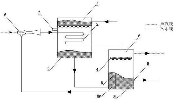
[0013] figure 1 Shown is a device diagram of a shower-excited heat-exchange sewage circulating flash steam generation system.

[0014] The steam generation system proposed by the present invention includes a water distribution tank 1, a shower-excited heat exchanger 2, a catchment tank 3, a sprayer 4, a flash tank 5 and a vapor-liquid ejector 6, and pipes are used to connect each device; The upper part of the exciter heat exchanger 2 is provided with a volatile gas discharge port 7, and the flash tank 5 is provided with a water baffle 8 and an overflow pipe 9; the steam generation system is driven by high-pressure steam to a vapor-liquid ejector 6, and the flash tank is sucked The non-flash saturated sewage gathered in 5 is heated and pressurized and sent to the shower type heat exc...


PUM


Abstract

The invention discloses a sprinkling type heat exchange sewage circulation flash steam generation system, and belongs to the technical field of waste heat utilization and sewage treatment. According to the steam generation system, a steam-liquid ejector adopts high-pressure steam to suck non-flash sewage gathered in a flash tank, and the non-flash sewage enters a spraying type heat exchanger to be heated after being pressurized and then is fed into a sprayer to be subjected to flash evaporation at the top of the flash tank; high-temperature sewage in the water distribution tank is heated by pressurized water in the sprinkling heat exchanger, is enriched in a water collecting tank, and is fed into the bottom of a flash tank to realize spewing depressurization flash evaporation; and saturated sewage which is not flashed in the flash tank is communicated with an injection inlet of the vapor-liquid injector through an outlet pipe at the bottom, so that circulating pressurized flash is realized. The steam generation system is driven by a small part of high-pressure steam, does not consume extra pump work, realizes gradient utilization of waste heat of medium-high-temperature sewage in a circulating pressurization mode, and generates continuous and stable medium-low-pressure saturated steam through up-and-down combined flash evaporation in a flash evaporation tank, so that a steam source is provided for seawater desalination, sewage treatment or other steam using processes, and the energy consumption is reduced. Waste heat utilization of sewage is achieved, and energy conservation and emission reduction are achieved.

Description

technical field [0001] The patent of the present invention relates to a shower-excited heat exchange sewage circulating flash steam generation system, which belongs to the technical fields of heavy oil thermal recovery, sewage treatment, seawater desalination and waste heat utilization. Background technique [0002] With the continuous development of petrochemical and energy utilization technology, my country's oil collection has entered the stage of heavy oil thermal recovery. The main technologies used in heavy oil thermal recovery are: steam huff and puff thermal recovery technology, steam-driven thermal recovery technology, and steam-assisted gravity drainage. Oil thermal recovery technology and sublayer combustion thermal recovery technology. [0003] Technology requires a lot of steam, fresh water. The steam source system that can supply medium and low pressure steam for thermal seawater desalination or sewage treatment plants such as large and medium-sized multi-effec...

Claims


Application Information

Patent Timeline
Patent Type & Authority Applications(China)
IPC IPC(8): F22B3/04F28D3/02F28D3/04
CPCF22B3/04F28D3/02F28D3/04
Inventor 杨勇张兴尧谢泽隆
Owner DALIAN UNIV OF TECH
Why Eureka
Try Eureka