
Grinding machine for punching die

A grinding machine and grinding mechanism technology, applied in grinding machines, manufacturing tools, grinding drive devices, etc., can solve problems such as low efficiency, dust emission, dust accumulation in molds, etc., and achieve the effect of increasing punching quality and uniform grinding

Pending Publication Date: 2022-06-24
南通炜冠机械模具有限公司
View PDF5 Cites 0 Cited by
  • Summary
  • Abstract
  • Description
  • Claims
  • Application Information

AI Technical Summary

Problems solved by technology

[0004]1. After the motor is tilted, only the contact surface between the mold and the grinding disc can be polished. When the mold is fully polished, the mold can only be rotated and then polished again. Low, and it is easy to grind unevenly on the surface of the mold, which affects the quality of subsequent punching;
[0005]2. When the grinding disc grinds the mould, more dust will be generated at the grinding disc, which will cause the dust to be discharged in the air, which will not only endanger the health of the operators , will also accumulate more dust on the mold, resulting in cumbersome follow-up cleaning

Method used


Image

  • Grinding machine for punching die
  • Grinding machine for punching die
  • Grinding machine for punching die

Examples


Embodiment Construction

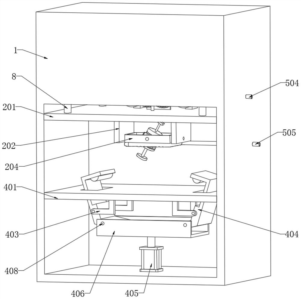
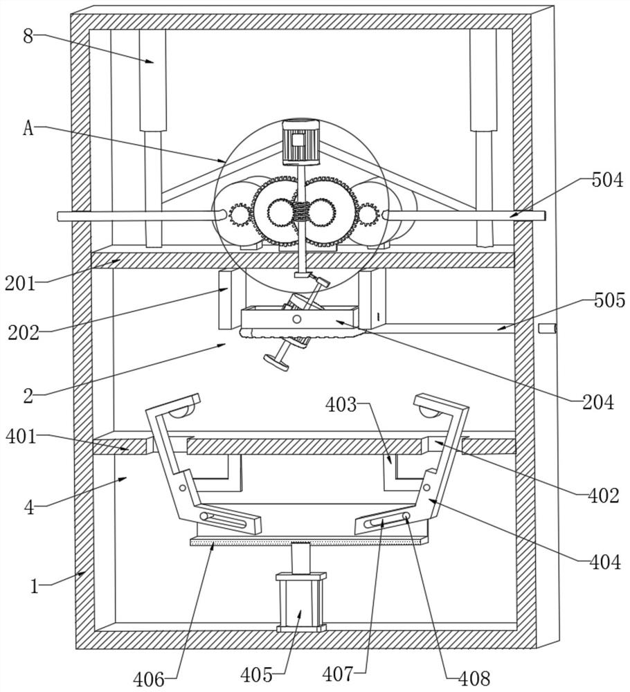
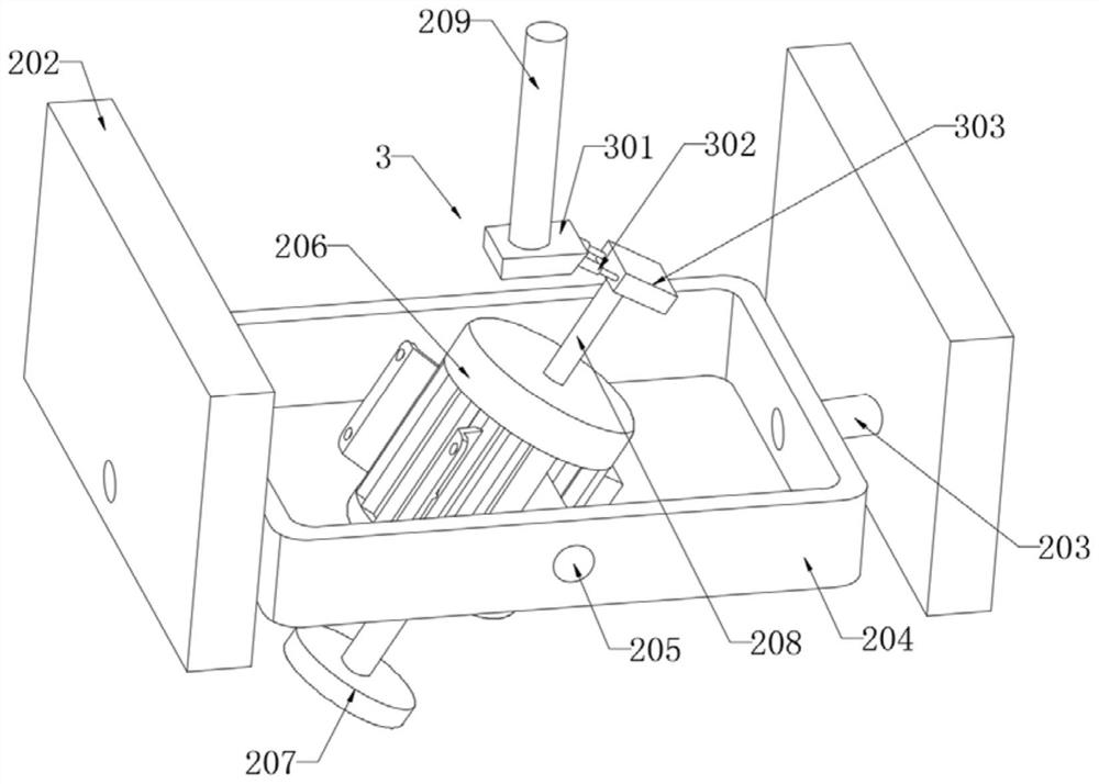
[0027] refer to figure 1 and 3 , a grinding machine for punching dies, comprising a casing 1, a grinding mechanism 2 for tilting the punching dies is provided in the casing 1, the grinding mechanism 2 comprises a horizontal plate 201 slidably connected to the inner wall of the casing 1, and the horizontal plate 201 The lower end is fixedly connected with two vertical plates 202 , and the side walls of the two vertical plates 202 are both connected to a ring frame 204 through the joint rotation of the first rotating shaft 203 . A servo motor 206 is connected, a grinding disc 207 is fixedly connected to the movable end of the servo motor 206, a fixing column 208 is fixedly connected to the side wall of the servo motor 206 away from the movable end, and a vertical rod 209 is rotatably connected to the side wall of the horizontal plate 201, and the lower end of the vertical rod 209 passes through The adjusting mechanism 3 is rotatably connected to one end of the fixing column 208...


PUM


Abstract

The grinding machine comprises a machine box, a grinding mechanism for obliquely grinding the punching die is arranged in the machine box, the grinding mechanism comprises a transverse plate connected to the inner wall of the machine box in a sliding mode, and two vertical plates are fixedly connected to the lower end of the transverse plate; the side walls of the two vertical plates are jointly and rotationally connected with an annular frame through first rotating shafts, the inner walls of the two sides, away from the first rotating shafts, of the annular frame are rotationally connected with servo motors through second rotating shafts, the movable ends of the servo motors are fixedly connected with grinding discs, and the side walls, away from the movable ends, of the servo motors are fixedly connected with fixing columns. By arranging the grinding mechanism, the grinding disc can rotate in the inclined state, then the grinding disc can comprehensively grind the notch of the punching groove in the die, grinding is uniform, the subsequent punching quality is improved, and the situation that when the die is comprehensively ground, the die can only be rotated and then ground again, and the efficiency is low is avoided.

Description

technical field [0001] The invention relates to the technical field of grinding machines, in particular to a grinding machine used for punching molds. Background technique [0002] After the punching die is used for a period of time, the punching edge of the die is gradually rounded and needs to be polished with a sander. [0003] In the patent "a bracket punching die lower die grinding machine" with the application number "201811317297.9", the solution drives the mounting seat to swing through the sector gear, so that the grinding disc can be tilted by rotating the motor, which can reduce the grinding of the grinding disc and the lower die. At the same time, manually rotating the chuck drives the lower mold to rotate, which is convenient for the grinding disc to tilt the lower mold for comprehensive grinding. However, this solution still has the following defects: [0004] 1. After the motor is tilted, only the contact surface of the mold and the grinding disc can be groun...

Claims


Application Information

Patent Timeline
IPC IPC(8): B24B19/20B24B41/06B24B47/00B24B41/04B24B47/22B24B47/12B24B55/06
CPCB24B19/20B24B41/06B24B47/00B24B41/04B24B47/22B24B47/12B24B55/06Y02P70/10
Inventor 李卫建
Owner 南通炜冠机械模具有限公司
Learn More