Percutaneous coronary intervention device for treating acute coronary syndrome
A coronary artery and syndrome technology, applied in the medical field, can solve problems such as excessive gas and blood vessel damage, and achieve the effect of improving accuracy, improving safety, and optimizing the allocation of operation time
- Summary
- Abstract
- Description
- Claims
- Application Information
AI Technical Summary
Problems solved by technology
Method used
Image
Examples
Embodiment 1
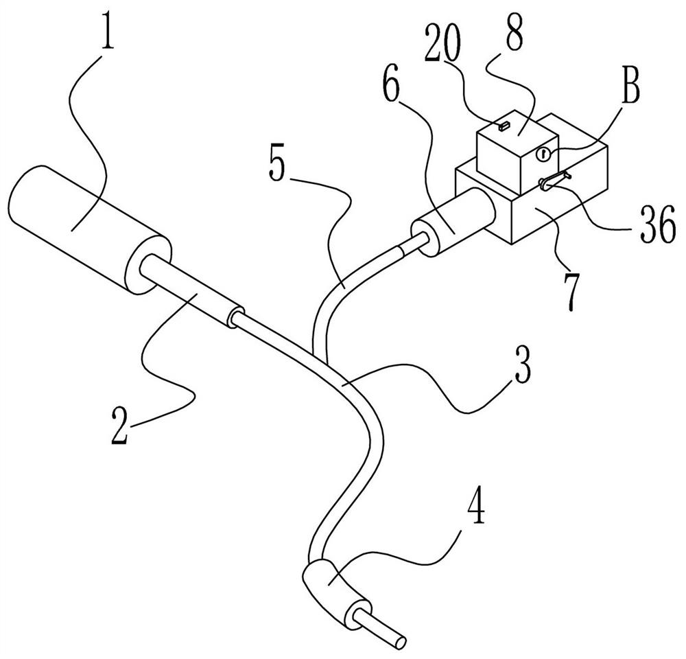
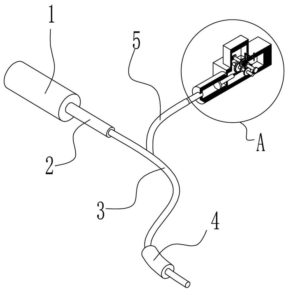
[0027] like figure 1 and 2 As shown, a percutaneous coronary intervention device for treating acute coronary syndrome includes a device main body 1, one end of the device main body 1 is mounted with a first catheter 2, and the first catheter 2 is away from one end of the device main body 1 A second catheter 3 is installed, the outer wall of the second catheter 3 is sleeved with a balloon 4, and the inner wall of the balloon 4 is provided with an inflation device; during treatment, the second catheter 3 and the balloon 4 can be placed along the The femoral artery and the blood vessel enter the coronary artery, and then the inside of the balloon 4 is inflated through the inflation device, so as to expand the blood vessel and realize the inflation of the inside of the balloon 4 .
[0028] like figure 2 and Image 6 , the inflatable device includes a fourth conduit 5 installed on the inner wall of the balloon 4, an injection device 6 is installed at one end of the fourth condu...
Embodiment 2
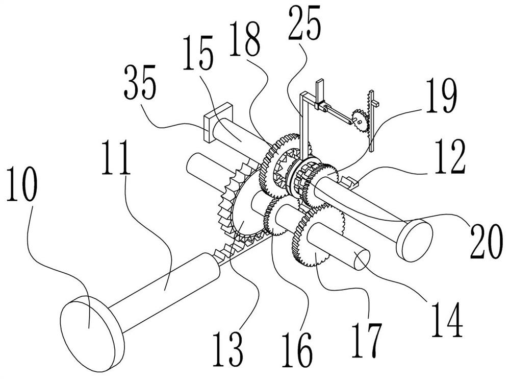
[0031] like image 3 As shown, this embodiment further describes Embodiment 1, the connecting mechanism includes a second gear 16 and a third gear 17 mounted on the outer wall of the first rotating shaft 14, and both the second gear 16 and the third gear 17 pass through The bearing is connected with the first rotating shaft 14, the side walls of the second gear 16 and the third gear 17 are respectively meshed with the fourth gear 18 and the fifth gear 19, and the fourth gear 18 and the fifth gear 19 are sleeved on the On the outer wall of the second rotating shaft 15, the fourth gear 18 and the fifth gear 19 are connected to the first rotating shaft 14 through bearings, and an adjustment mechanism is arranged between the fourth gear 18 and the fifth gear 19, which can be adjusted between the fourth gear 18 and the fifth gear 19. When it is necessary to control the accuracy of gas entry, the sixth gear 21 can be meshed with the fifth gear 19 through the adjusting mechanism, so ...
Embodiment 3
[0034] like image 3 , Figure 4 and Figure 5 As shown, this embodiment further describes Embodiment 1. The adjusting mechanism includes a sixth gear 21 disposed on the outer wall of the second rotating shaft 15, and the sixth gear 21 is slidably connected to the second rotating shaft 15, so The side wall of the sixth gear 21 is provided with an annular groove 23, an arc-shaped block 24 is installed on the inner wall of the annular groove 23, and a second connecting rod 25 is installed on the top of the arc-shaped block 24. The second connecting rod A third connecting rod 26 is installed on one end of the 25 away from the arc-shaped block 24 , a third connecting rod 26 is installed on one side of the third connecting rod 26 , and one end of the third connecting rod 26 away from the second connecting rod 25 is installed There is a second control mechanism, which can drive the third connecting rod 26 to slide through the second control mechanism when adjusting the speed of ga...
PUM
 Abstract
Description
Claims
Application Information
 - R&D
- Intellectual Property
- Life Sciences
- Materials
- Tech Scout
- Unparalleled Data Quality
- Higher Quality Content
- 60% Fewer Hallucinations
Browse by: Latest US Patents, China's latest patents, Technical Efficacy Thesaurus, Application Domain, Technology Topic, Popular Technical Reports.
© 2025 PatSnap. All rights reserved.Legal|Privacy policy|Modern Slavery Act Transparency Statement|Sitemap|About US| Contact US: help@patsnap.com


