Heat conduction device and heat conduction method for LED high-power lighting lamp

A lighting fixture, high-power technology, applied in lighting devices, cooling/heating devices for lighting devices, lighting and heating equipment, etc., to achieve the effects of accelerating air flow, increasing heat dissipation efficiency, and preventing incomplete contact

Active Publication Date: 2022-06-17
SHENZHEN MESTER OPTOELECTRONICS TECH CO LTD
View PDF14 Cites 0 Cited by
  • Summary
  • Abstract
  • Description
  • Claims
  • Application Information

AI Technical Summary

Problems solved by technology

[0003] At present, when high-power LED lighting fixtures dissipate heat, they generally conduct and dissipate heat through a heat sink composed of heat pipes and heat sinks to reduce the temperature of the lamps. , the temperature of the radiator and heat pipe will rise rapidly, and then the temperature reaches a certain range. In order to improve the service life of the lamp, it is necessary to speed up the heat dissipation of the radiator and heat pipe, so as to reduce the temperature of the lamp and realize the improvement of the use of LED lighting lamps. The effect of life; in view of this, we propose a heat conduction device and heat conduction method for LED high-power lighting fixtures

Method used


Image

  • Heat conduction device and heat conduction method for LED high-power lighting lamp
  • Heat conduction device and heat conduction method for LED high-power lighting lamp
  • Heat conduction device and heat conduction method for LED high-power lighting lamp

Examples


Embodiment Construction

[0031] The technical solutions in the embodiments of the present invention will be clearly and completely described below with reference to the accompanying drawings in the embodiments of the present invention. Obviously, the described embodiments are only a part of the embodiments of the present invention, but not all of the embodiments. Based on the embodiments of the present invention, all other embodiments obtained by those of ordinary skill in the art without creative efforts shall fall within the protection scope of the present invention.

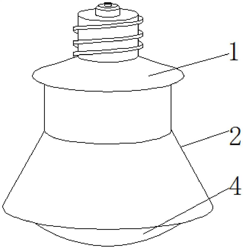
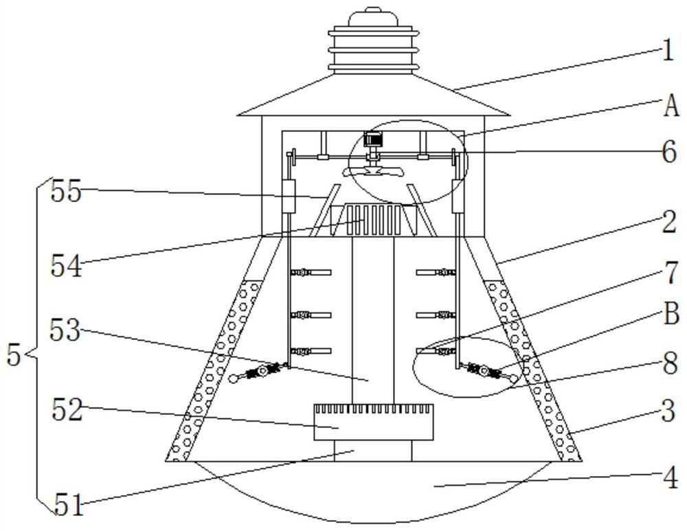
[0032] see Figure 1-Figure 6 , the present invention provides a technical solution: a heat conduction device for an LED high-power lighting fixture, including a tower-shaped lamp holder 1, through the use of the tower-shaped lamp holder 1, the device can be easily installed by the staff, and the lower part of the tower-shaped lamp holder 1 is fixed. The casing 2 is connected, and the use of the casing 2 can protect the lighting fixtu...


PUM


Abstract

The invention discloses a heat conduction device and a heat conduction method of an LED high-power lighting lamp, and relates to the technical field of lighting devices. According to the LED high-power lighting lamp heat conduction device and the heat conduction method thereof, the LED high-power lighting lamp heat conduction device comprises a tower-shaped lamp holder, a shell is fixedly connected to the lower portion of the tower-shaped lamp holder, a filter screen is arranged on the side wall of the shell, a lampshade is fixedly installed in the shell, a heat conduction assembly is arranged in the shell, and a heat dissipation assembly is arranged above the heat conduction assembly. A swing assembly and an anti-blocking assembly are arranged below the heat dissipation assembly. According to the heat conduction device for the LED high-power lighting lamp and the heat conduction method of the heat conduction device, the heat conduction assembly, the heat dissipation assembly, the swing assembly and the beating assembly are used in cooperation, the heat dissipation effect of a radiator is better, meanwhile, heat dissipation can be conducted on a heat conduction pipe, and the possibility that a filter screen is blocked by dust is prevented; normal air circulation and heat dissipation can be carried out, and the service life of the lighting lamp is prolonged.

Description

technical field [0001] The invention relates to the technical field of lighting devices, in particular to a heat conduction device for an LED high-power lighting fixture and a heat conduction method thereof. Background technique [0002] High-power LED lighting fixtures have brought another leap in the history of human lighting. However, high-power LEDs face a heat dissipation problem. 70% to 85% of the electrical energy input by the existing LED is converted into heat, and the LED chip is very small. If the heat dissipation is poor, the temperature of the chip will rise, causing uneven thermal stress distribution. , The luminous efficiency of the chip is reduced, and the lasing efficiency of the phosphor powder is reduced, which leads to the rapid deterioration of the LED chip and the shortened life of the device. The heat dissipation of the chip is the focus of its technical problems. , Shorten the life of LED lights, and burn chips and LED bulbs. Therefore, there is a l...

Claims


Application Information

Patent Timeline
Patent Type & Authority Applications(China)
IPC IPC(8): F21K9/232F21V29/503F21V29/60F21V29/67F21V29/76F21V29/83B01D46/76F21Y115/10
CPCF21K9/232F21V29/503F21V29/67F21V29/76F21V29/83F21V29/60F21Y2115/10
Inventor 李建平马二华
Owner SHENZHEN MESTER OPTOELECTRONICS TECH CO LTD
Why Eureka
Try Eureka