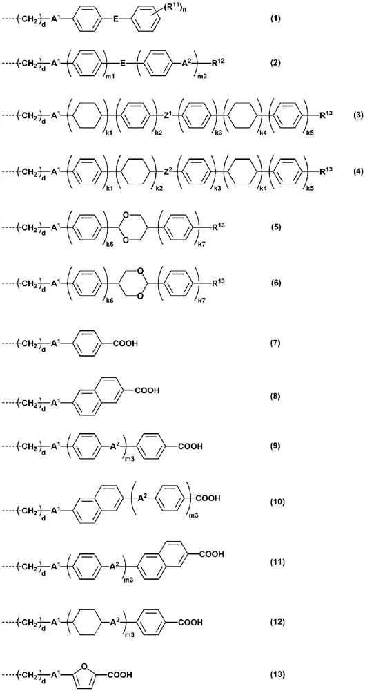
Manufacturing method of patterned single-layer phase difference material
A phase difference material and manufacturing method technology, applied in the direction of instruments, polarizing elements, optical elements, etc., to achieve the effect of suppressing whitening
Pending Publication Date: 2022-06-10
NISSAN CHEM IND LTD
View PDF8 Cites 0 Cited by
- Summary
- Abstract
- Description
- Claims
- Application Information
AI Technical Summary
Problems solved by technology
[0005] On the other hand, in an alignment film using a polymer containing a photocrosslinking site, it is known to use an exposure mask to produce a patterned monolayer based on this material In the case of retardation film, turbidity (HAZE) of the part not exposed to ultraviolet rays becomes a problem
Method used
View moreImage
Smart ImageViewing Examples
Examples
preparation example Construction
Embodiment
Synthetic example
Login to View More PUM
| Property | Measurement | Unit |
|---|---|---|
| wavelength | aaaaa | aaaaa |
| wavelength | aaaaa | aaaaa |
Abstract
The present invention provides a method for producing a patterned single-layer phase difference material, which comprises: (I) a step for forming a coating film by applying a polymer composition containing a liquid crystal polymer having an orientation that increases as the amount of exposure is lower than the optimum amount of exposure and that increases as the amount of exposure is higher than the optimum amount of exposure; a property in which the orientation is reduced as the exposure amount is greater under an exposure amount higher than the optimal exposure amount; (II) a step in which the coating film obtained in step (I) is irradiated twice with ultraviolet light to produce a high-anisotropy region having high optical anisotropy by irradiation with polarized ultraviolet light at least once across a mask and a low-anisotropy region having high optical anisotropy by irradiation with polarized ultraviolet light at least once. The low-anisotropy region has relatively low optical anisotropy by making the amount of ultraviolet light insufficient in a region lower than the optimal exposure amount and excessive in a region higher than the optimal exposure amount; and (III) a step for obtaining a phase difference material by heating the coating film obtained in step (II).
Description
technical field [0001] The invention relates to a method for manufacturing a patterned single-layer retardation material and the single-layer retardation material. In detail, the present invention relates to a patterned single-layer retardation material obtained from a composition comprising a liquid crystalline polymer, wherein the liquid crystalline polymer has: The more the amount is, the more the orientation is increased, and the more the exposure is higher than the optimum exposure, the more the orientation is reduced. The above-mentioned liquid crystal polymers can be preferably used for applications such as display devices and recording materials. A material having optical characteristics can be preferably used in optical compensation films such as polarizing plates and phase difference plates for liquid crystal displays. Background technique [0002] In order to improve the display quality and reduce the weight of liquid crystal display devices, there is an increasi...
Claims
Login to View More Application Information
Patent Timeline
 Patent Type & Authority Applications(China)
IPC IPC(8): G02F1/13363G02B5/30C08F246/00
CPCG02F1/13363G02B5/3016C08F246/00G02B5/30
Inventor 藤枝司根木隆之
Owner NISSAN CHEM IND LTD
- R&D Engineer
- R&D Manager
- IP Professional
- Industry Leading Data Capabilities
- Powerful AI technology
- Patent DNA Extraction
Learn More Browse by: Latest US Patents, China's latest patents, Technical Efficacy Thesaurus, Application Domain, Technology Topic, Popular Technical Reports.
© 2024 PatSnap. All rights reserved.Legal|Privacy policy|Modern Slavery Act Transparency Statement|Sitemap|About US| Contact US: help@patsnap.com


