Sonar control circuit

A control circuit and sonar technology, applied in the direction of comprehensive factory control, sound wave re-radiation, electrical digital data processing, etc., can solve the problem of sound wave sample point calculation without complex signal processing, low processing performance, less data acquisition and monitoring channels, etc. problems, to achieve the effect of rich communication interfaces, strong processing performance, and fast real-time response

Pending Publication Date: 2022-06-03
HAIYING ENTERPRISE GROUP
View PDF0 Cites 0 Cited by
  • Summary
  • Abstract
  • Description
  • Claims
  • Application Information

AI Technical Summary

Problems solved by technology

1) The communication interface is single and the number is small: the traditional sonar control circuit mainly relies on the serial port to realize the communication, and the transmitted data includes the azimuth angle, pitch angle, roll angle, pressure, temperature and humidity information of the sonar system, etc., and the serial port communication exists The shortcomings of low communication rate, short transmission distance and poor reliability
[0004] 2) Low processing performance and poor real-time response: The traditional sonar control circuit mainly uses a single-chip microcomputer as a processor. The main frequency of the single-chip microcomputer usually does not exceed 200MHz, and it cannot perform multi-tasking mode
It can only perform simple data acquisition and control work, and does not have the functions of complex signal processing and calculation of sound wave sample points
[0005] 3) Does not have log and key data recording functions: the traditional sonar control cir

Method used


Image

  • Sonar control circuit
  • Sonar control circuit
  • Sonar control circuit

Examples


Embodiment 1

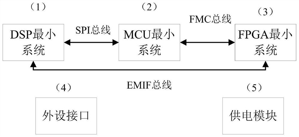
see Figures 1~10 As shown, this embodiment specifically discloses and provides a technical solution for a sonar control circuit, including:

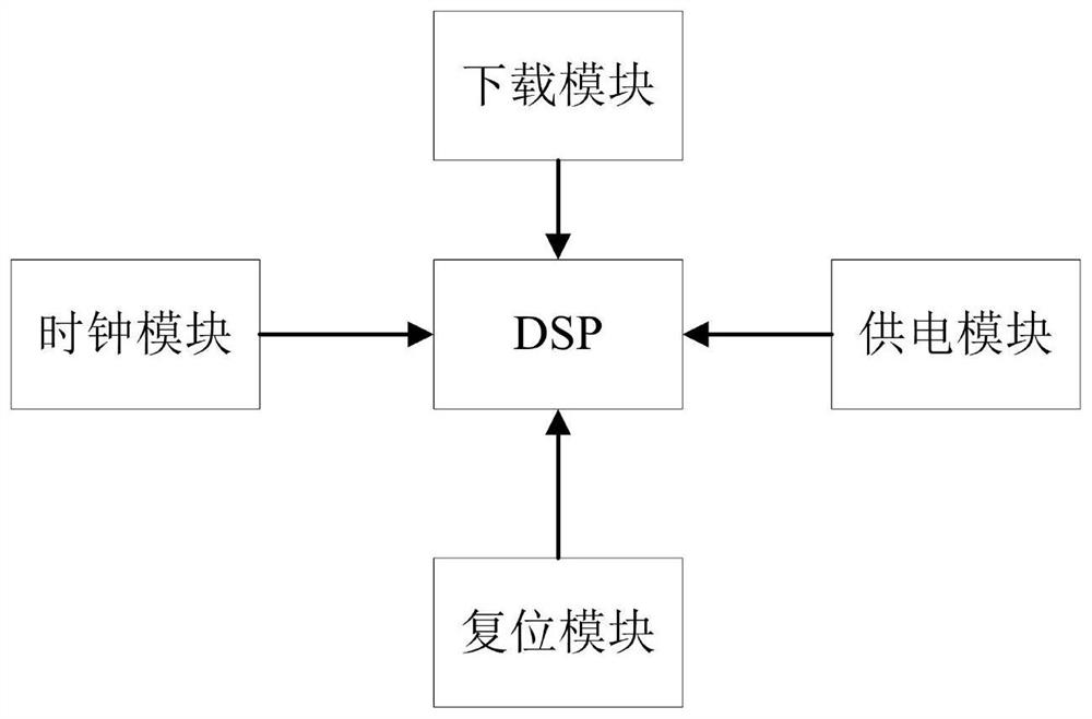
DSP minimum system 1: The main function is to realize complex sample emission signal generation, PWM generation, and complex signal processing;

MCU minimum system 2: The main function is to realize data communication, acquisition and recording;

FPGA minimum system 3: The main function realizes multi-channel data acquisition and control;

Peripheral interface 4: Provide all data collection, transmission and recording;

Power supply module 5: Provide stable and reliable power supply for the entire sonar control circuit.

[0031] DSP minimum system 1 such as figure 2 As shown: the DSP minimum system 1 and the MCU minimum system 2 communicate through the SPI bus, and the MCU minimum system 2 and the FPGA minimum system 3 realize data transmission through the FMC parallel bus. Data communication is implemented between the DSP minimum sy...


PUM


Abstract

The invention relates to the technical field of underwater acoustic signal control, in particular to a sonar control circuit. Comprising a DSP minimum system which is mainly used for realizing complex sample emission signal generation, PWM (Pulse Width Modulation) generation and complex signal processing; the MCU minimum system is mainly used for realizing data communication, acquisition and recording; the FPGA minimum system is mainly used for realizing multi-channel data acquisition and control; the peripheral interface is used for acquiring, transmitting and recording all data; the power supply module provides a stable and reliable power supply for the whole sonar control circuit; the DSP minimum system is communicated with the MCU minimum system in an SPI bus mode, the MCU minimum system is in data transmission with the FPGA minimum system in an FMC parallel bus mode, and the DSP minimum system is in data communication with the FPGA minimum system in an EMIF parallel bus mode. A command of a display and control console can be received according to a default set signal sample or through a network interface, a CAN bus interface and an RS422 bus interface, and a transmitting signal source is generated after the command is analyzed.

Description

technical field [0001] The invention relates to the technical field of underwater acoustic signal control, in particular to a sonar control circuit. Background technique [0002] The basic situation of traditional technology: underwater communication, detection, target recognition is currently the most effective way to complete through sonar, the current sonar can be loaded on different application platforms, including UUV, AUV, USV, ships, frogmen, underwater robots, etc. A complete sonar system mainly includes three parts: transmitting, receiving and controlling. The traditional sonar control circuit mainly relies on single chip microcomputer to realize the functions of sonar transmission, reception and control mainly through data acquisition, serial communication, signal source PWM and other functions. [0003] The traditional sonar control circuit mainly has the following shortcomings: 1) The communication interface is single and the number is small: the traditional ...

Claims


Application Information

Patent Timeline
IPC IPC(8): G01S7/52G01S15/88G06F13/40G06F13/42
CPCG01S7/52G01S15/88G06F13/4282G06F13/4068Y02P90/02
Inventor 杨凯强
Owner HAIYING ENTERPRISE GROUP
Why Eureka
Try Eureka