
Permanent magnet synchronous motor static initial position estimation method and stator inductance identification method

A technology of permanent magnet synchronous motor and initial position, which is applied to the control of generators, motor generators, AC motors, etc. It can solve the problems of high sampling and signal conditioning circuits, complex calculations, and low precision, so as to ensure accurate performance, ensure data accuracy, and reduce data loss

Pending Publication Date: 2022-05-31
CRRC QINGDAO SIFANG ROLLING STOCK RES INST
View PDF1 Cites 1 Cited by
  • Summary
  • Abstract
  • Description
  • Claims
  • Application Information

AI Technical Summary

Problems solved by technology

Such as the look-up table method, which uses the pre-obtained current response and rotor angle comparison table to obtain the rotor position. This method requires a large number of experiments in advance, and the operation is relatively complicated and the accuracy is not high; another example is the inductance matrix method, which is obtained through the transient current response. The inductance matrix, and then the rotor position is calculated by the inductance matrix. This method is complex to calculate, and due to sampling deviation, inductance matrix conversion, etc., it has high requirements for sampling and signal conditioning circuits.

Method used


Image

  • Permanent magnet synchronous motor static initial position estimation method and stator inductance identification method
  • Permanent magnet synchronous motor static initial position estimation method and stator inductance identification method
  • Permanent magnet synchronous motor static initial position estimation method and stator inductance identification method

Examples


Embodiment Construction

[0041]In order to make the technical problems, technical solutions and beneficial effects to be solved by the present invention clearer, the present invention will be further described in detail below in conjunction with the accompanying drawings and embodiments. It should be understood that the specific embodiments described here are only used to explain the present invention, not to limit the present invention.

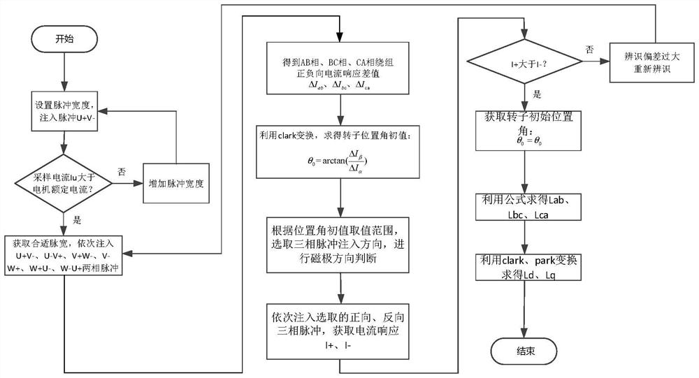
[0042] The present invention provides a method for estimating the static initial position of a permanent magnet synchronous motor and an inductance identification method, and the overall process refers to figure 2 , which can be used in auxiliary control of direct-drive permanent magnet wind turbines to solve the problems of initial rotor position estimation and stator inductance identification.

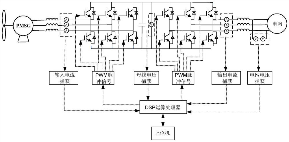
[0043] The structure of the direct drive permanent magnet wind turbine system is as follows: figure 1 As shown, it mainly includes the following parts: machine-side inpu...


PUM


Abstract

The invention provides a permanent magnet synchronous motor static initial position estimation method and a stator inductance identification method. A rated positive pulse voltage and a rated negative pulse voltage are sequentially injected into windings of an AB phase, a BC phase and a CA phase of a motor, response current values of the phases under the rated positive pulse voltage and the rated negative pulse voltage are recorded, and current response difference values delta Iab, delta Ibc and delta Ica of the AB phase, the BC phase and the CA phase under a three-phase static coordinate system are calculated; performing Clark transformation on the current response difference values of all phases to obtain current response difference values delta I alpha and delta I beta under the alpha-beta axis two-phase static coordinate system; and calculating the initial position theta of the rotor based on the delta I alpha and the delta I beta. And calculating the stator inductance of the permanent magnet synchronous motor based on the initial position of the rotor obtained through calculation. Through coordinate transformation and solution, the rotor position is directly obtained through current pulse response, an intermediate conversion link is omitted, data loss can be reduced, and data precision is guaranteed.

Description

technical field [0001] The invention relates to the technical field of motor control, and relates to a static initial position estimation method of a permanent magnet synchronous motor and a stator electrical identification method. Background technique [0002] Direct-drive permanent magnet wind turbines have stable performance and high economic benefits, and are widely used in major wind farms. However, due to factors such as the size of the unit, it is difficult to obtain sufficient installation space for components such as position sensors, so the sensorless control strategy has begun to become increasingly popular. It is increasingly used in the field of wind power. The sensorless control strategy of permanent magnet synchronous motor includes observer control, switching control, variable structure control and other control methods, and these methods need to realize accurate estimation of the initial rotor position. At the same time, the accurate identification of the i...

Claims


Application Information

Patent Timeline
Patent Type & Authority Applications(China)
IPC IPC(8): H02P21/18H02P21/14H02P25/024
CPCH02P21/18H02P21/14H02P25/024
Inventor 位俊雷赵振华胡冰崔晓光张利军邵春伟赵栋咸粤飞
Owner CRRC QINGDAO SIFANG ROLLING STOCK RES INST
Learn More