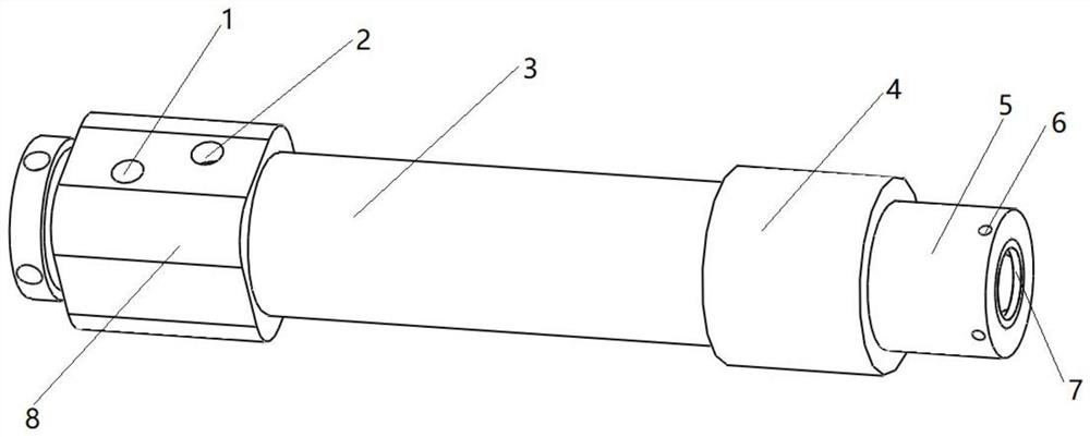
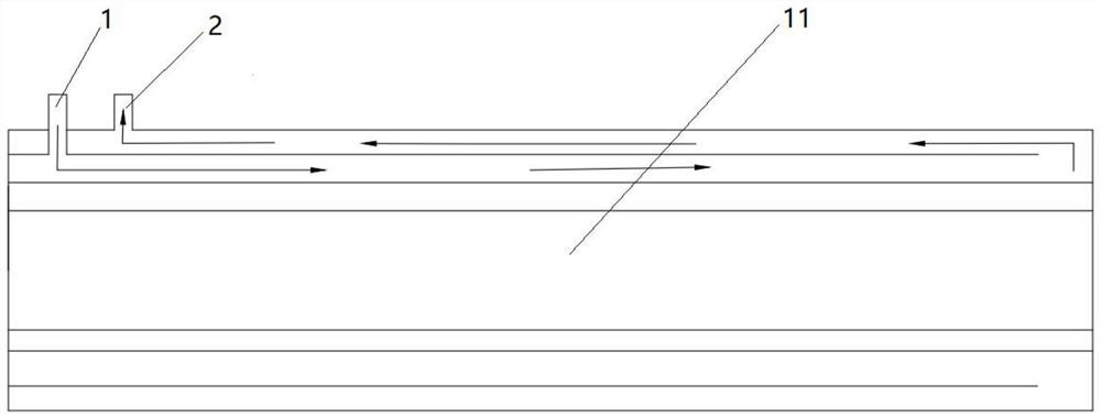
Crystallizer, copper melting furnace and copper-clad steel production line with copper melting furnace

A crystallizer and copper melting furnace technology, applied in the direction of furnace, furnace material, furnace cooling, etc., can solve the problems of uneven copper layer thickness, poor bonding, temperature difference, etc., and achieve the effect of uniform copper layer thickness

Pending Publication Date: 2022-05-31
金合同盛(天津)企业管理咨询中心(有限合伙)
View PDF0 Cites 0 Cited by
  • Summary
  • Abstract
  • Description
  • Claims
  • Application Information

AI Technical Summary

Problems solved by technology

[0004] Therefore, the technical problem to be solved in the present invention is to overcome the temperature difference between the crystallizer and the copper liquid in the prior art, which affects the complete contact between the copper liquid and the steel wire, and the uneven thickness of the copper layer covering the steel wire is prone to occur. Combining the defects of poor and poor cladding quality, thereby providing a crystallizer, copper melting furnace and copper clad steel production line having the same

Method used


Image

  • Crystallizer, copper melting furnace and copper-clad steel production line with copper melting furnace
  • Crystallizer, copper melting furnace and copper-clad steel production line with copper melting furnace
  • Crystallizer, copper melting furnace and copper-clad steel production line with copper melting furnace

Examples


Embodiment Construction

[0032] The technical solutions of the present invention will be clearly and completely described below in conjunction with the accompanying drawings. Apparently, the described embodiments are some of the embodiments of the present invention, but not all of them. Based on the embodiments of the present invention, all other embodiments obtained by persons of ordinary skill in the art without making creative efforts belong to the protection scope of the present invention.

[0033] In the description of the present invention, it should be noted that the terms "center", "upper", "lower", "left", "right", "vertical", "horizontal", "inner", "outer" etc. The indicated orientation or positional relationship is based on the orientation or positional relationship shown in the drawings, and is only for the convenience of describing the present invention and simplifying the description, rather than indicating or implying that the referred device or element must have a specific orientation, ...


PUM

PropertyMeasurementUnit
melting pointaaaaaaaaaa

Abstract

The invention relates to the technical field of production of copper-clad steel manufactured through a horizontal continuous casting process, in particular to a crystallizer, a copper melting furnace and a copper-clad steel production line with the crystallizer and the copper melting furnace. A crystallizer comprises a fixing sleeve, a first through hole and a second through hole, the first end of the cooling pipe is arranged in the first through hole, and the cooling pipe is provided with a channel allowing the steel wire to penetrate through; the pouring mold is partially arranged in the first through hole and is in butt joint with the first end of the cooling pipe, the pouring mold is provided with a second through hole allowing the steel wire to penetrate through, a gap is reserved between the steel wire and the inner wall of the second through hole, and the side wall, exposed out of the first through hole, of the pouring mold is provided with at least one pouring hole allowing copper liquid to flow in. The pouring hole is communicated with the second through hole, and the axes of the pouring hole and the second through hole are perpendicular to each other, so that copper liquid entering through the pouring hole covers the surfaces of the steel wires in the pouring mold and the cooling pipe. The problems that due to the fact that the temperature difference exists between the crystallizer and molten copper, complete contact between the molten copper and the steel wire is affected, and the thickness of a copper layer covering the steel wire is not uniform are solved.

Description

technical field [0001] The invention relates to the technical field of copper-clad steel production by a horizontal continuous casting process, in particular to a crystallizer, a copper melting furnace and a copper-clad steel production line with the same. Background technique [0002] Copper-clad steel bimetal composite material, also known as copper-clad steel (or copper-clad steel), is a composite conductor made of copper and steel through special processing. The composite conductor has both high strength and excellent performance of steel. The elasticity, large thermal resistance and high magnetic permeability, as well as the good electrical conductivity and excellent corrosion resistance of copper, are widely used in many fields such as electrical and electronic. [0003] At present, there are mainly three methods of coating copper on the surface of steel wire in China (electroplating method, coating method and horizontal continuous casting coating method). The problem...

Claims


Application Information

Patent Timeline
Patent Type & Authority Applications(China)
IPC IPC(8): B22D11/055B22D19/16F27B17/00F27D9/00
CPCB22D11/055B22D11/004B22D19/16F27B17/00F27D9/00F27D2009/0083F27M2001/015Y02P10/20
Inventor 王伟
Owner 金合同盛(天津)企业管理咨询中心(有限合伙)
Why Eureka
Try Eureka