Composite electric wire and method for manufacturing composite electric wire

A manufacturing method and electric wire technology, applied in the direction of cable/conductor manufacturing, conductive core parts, equipment for manufacturing conductive/semiconductive layers, etc., can solve the problems of manufacturing method and complex structure, and achieve easy manufacturing and plasticity Large, to achieve the effect of thinning

Pending Publication Date: 2022-05-27
DELTA PLUS CO LTD
View PDF1 Cites 0 Cited by
  • Summary
  • Abstract
  • Description
  • Claims
  • Application Information

AI Technical Summary

Problems solved by technology

Although the wire can also be reduced in diameter, the manufacturing method and structure become complicated

Method used


Image

  • Composite electric wire and method for manufacturing composite electric wire
  • Composite electric wire and method for manufacturing composite electric wire
  • Composite electric wire and method for manufacturing composite electric wire

Examples


Embodiment 1

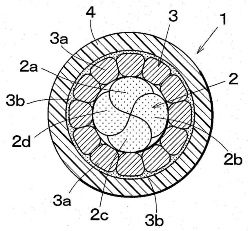
[0030] figure 1 It is a cross-sectional view of the composite electric wire 1 of Example 1. A conductive layer 3 composed of a copper wire 3 a and a tin layer 3 b is arranged around the core wire 2 , and an insulating coating layer 4 is further arranged around the conductive layer 3 , which has flexibility as a whole.

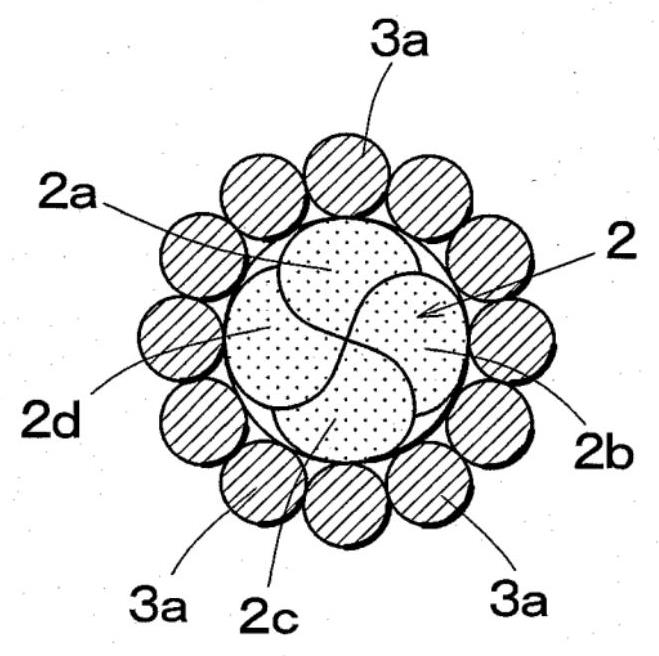
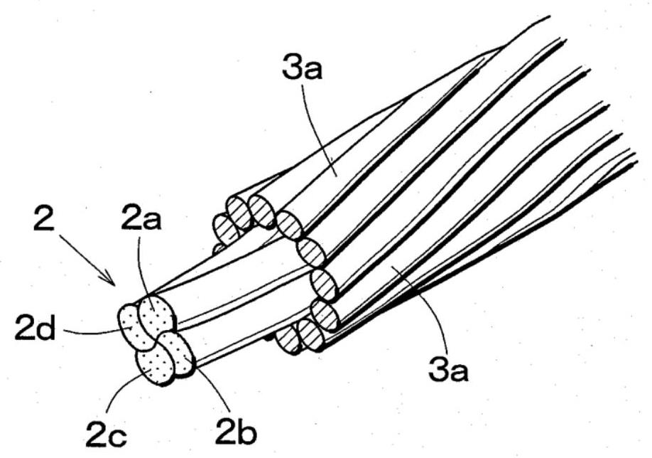
[0031] The core wire 2 is formed by twisting, for example, four middle wires 2a to 2d, and each of the middle wires 2a to 2d is formed by twisting a polymer strand made of a synthetic resin material such as 48 aramid fibers. The diameter of these strands is, for example, 12 μm, and the diameter of the core wire 2 is about 200 μm. In addition, the aramid fiber has the characteristics of being light in weight, high in strength and high in flexibility, and not conductive.

[0032] The conductive layer 3 includes: a conductive metal wire with a high melting point, such as a copper wire (Cu: melting point 1085°C) 3a; and a low melting point metal, which is a metal...

Embodiment 2

[0047] Figure 8 It is a cross-sectional view of the composite electric wire 1' of Example 2. In the composite electric wire 1 ′, a coating layer 5 is provided around the core wire 2 , a conductive layer 3 composed of a copper wire 3 a and a tin layer 3 b is arranged outside the coating layer 5 , and an insulating layer is provided around the conductive layer 3 . cladding 4.

[0048] The structure of the core wire 2 is the same as that of Example 1, but the coating layer 5 is provided around the core wire 2. The coating layer 5 is made of, for example, a polyester resin and has a thickness of several μm. In addition, the conductive layer 3 and the insulating coating layer 4 have the same structure as that of the first embodiment.

[0049] Figure 9It is an explanatory drawing of the manufacturing process of this composite electric wire 1'. Including: the coating step E, coating the coating layer 5 around the core wire 2; the metal wire winding step A, then winding the copp...


PUM

PropertyMeasurementUnit
diameteraaaaaaaaaa
diameteraaaaaaaaaa

Abstract

The invention relates to a composite electric wire and a manufacturing method thereof. The problem to be solved by the present invention is to obtain a composite electric wire having strong conductivity and high plasticity. A conductive layer (3) is disposed around a central core wire (2), and an insulating coating layer (4) is provided around the conductive layer (3), thereby forming a composite electric wire having an outer diameter of about 500 mm. The core wire (2) is formed by twisting, for example, four center wires (2a-2d), and each center wire (2a-2d) is formed by twisting, for example, strands composed of 48 aramid fibers. The diameter of the strands is, for example, 12 [mu] m, and the diameter of the core wire (2) is about 200 [mu] m. As the conductive layer (3), 12 copper wires (3a), for example, having a diameter of 80 [mu] m, are closely wound around the core wire (2) in a spiral shape, and the peripheries of the copper wires (3a) are formed into a circle by tightening. Furthermore, the copper wires (3a) are covered by a tin layer (3b), which is a low-melting-point metal, with a thickness of several [mu] m, and the copper wires (3a) are adhered to each other by the tin layer (3b).

Description

technical field [0001] The present invention relates to a composite electric wire having a small diameter and applicable to small crimp connection terminals, and a method for manufacturing the composite electric wire. Background technique [0002] In recent years, there has been a strong demand for weight reduction and miniaturization of components used in various electrical devices, for example. The number of signal wirings also increases with the use of a plurality of sensors and the like, and further miniaturization of electrical connectors for connecting wirings is required. [0003] In order to reduce the size of the electrical connector, it is necessary to reduce the size of the connecting terminal used for the electrical connector and reduce the diameter of the electric wire. Recently, connection terminals with a connection diameter of 1 mm or less have been used, so wires with a diameter of about 0.5 mm are required. [0004] For this reason, a so-called fiber elec...

Claims


Application Information

Patent Timeline
Patent Type & Authority Applications(China)
IPC IPC(8): H01B5/14H01B1/02H01B3/30H01B7/282H01B13/00H01B13/06H01B13/30
CPCH01B5/14H01B7/2825H01B1/02H01B3/30H01B13/0026H01B13/06H01B13/30H01B7/1825H01B7/0009H01B13/0292H01B13/0207
Inventor 安保次雄伊藤真康岛沢胜次石田英司
Owner DELTA PLUS CO LTD
Why Eureka
Try Eureka