
FP interference type sound wave detector and sound wave detection method

A sound wave detector and sound wave detection technology, applied in the direction of measuring ultrasonic/sonic/infrasonic waves, instruments, measuring devices, etc., can solve the problems of phase jump, complex demodulation algorithm, limited small signal demodulation, etc., and achieve high precision, Excellent demodulation performance and improved sensitivity

Active Publication Date: 2022-05-27
HUAZHONG UNIV OF SCI & TECH +1
View PDF9 Cites 0 Cited by
  • Summary
  • Abstract
  • Description
  • Claims
  • Application Information

AI Technical Summary

Problems solved by technology

The phase carrier generation and demodulation method needs to generate a strict carrier, and the demodulation algorithm is relatively complicated; the 3×3 coupler method needs to use a 3×3 coupler, and it is necessary to strictly control the coupling ratio of 1:1:1 and the phase difference of each output terminal is 120°; the improved 3×3 coupling method needs to cooperate with algorithms such as ellipse fitting, which can relax the requirements for coupling ratio and phase difference, but the demodulation of small signals is very limited
For the spectrum demodulation algorithm, the interferometric phase is obtained by calculating the interference spectrum of the interferometer, which has the advantages of high precision, strong anti-interference, and little influence by system noise. It is suitable for demodulating low-frequency signals, but involves the calculation of the reverse calculation phase steps, often introduces the problem of phase jumps

Method used


Image

  • FP interference type sound wave detector and sound wave detection method
  • FP interference type sound wave detector and sound wave detection method
  • FP interference type sound wave detector and sound wave detection method

Examples


Embodiment Construction

[0036] In order to make the objectives, technical solutions and advantages of the present invention clearer, the present invention will be further described in detail below with reference to the accompanying drawings and embodiments. It should be understood that the specific embodiments described herein are only used to explain the present invention, but not to limit the present invention. In addition, the technical features involved in the various embodiments of the present invention described below can be combined with each other as long as they do not conflict with each other.

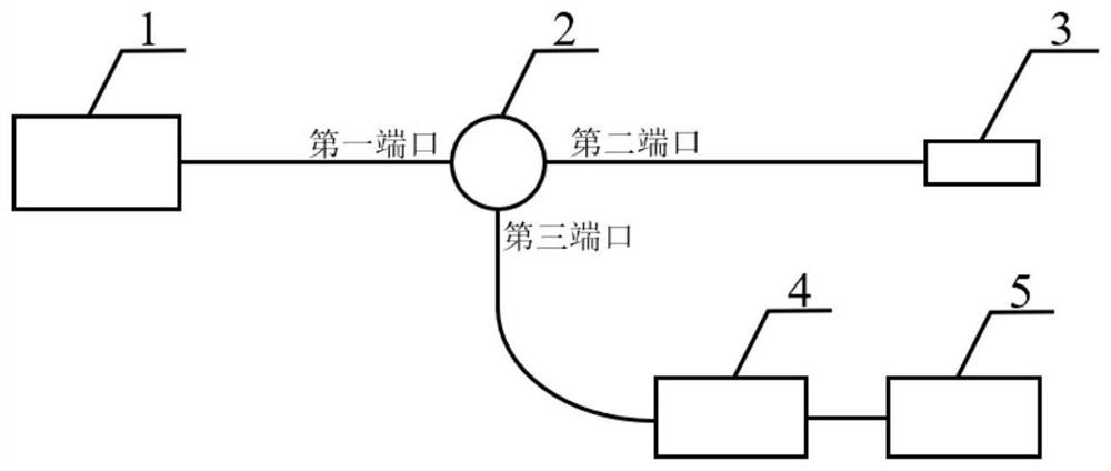
[0037] Aiming at the high sensitivity requirement of the existing acoustic wave detection, the present invention proposes an acoustic wave detection system based on high-precision FP interference and a phase demodulation algorithm. Multi-beam interference occurs between them to form an FP cavity, and the improved Fourier phase demodulation algorithm is used to demodulate the high-order peak of the F...


PUM


Abstract

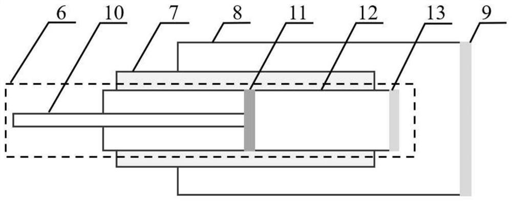
The invention discloses an FP interference type sound wave detector and a sound wave detection method, and belongs to the technical field of sound wave detection, and the FP interference type sound wave detector comprises a light source, an optical fiber circulator, an FP sensing head, a spectrum real-time acquisition module and a signal processing demodulation module. The FP sensing head is composed of an optical fiber collimator, a ceramic ferrule, a metal sleeve and a thin film, and the optical fiber collimator is designed to a certain extent. By using the improved Fourier phase demodulation algorithm, the spectral phase variation in direct proportion to the cavity length variation can be obtained, and the improved demodulation algorithm greatly widens the dynamic range of the detection system. For an extrinsic high-fineness FP sensor, the phase demodulation method provided by the invention can realize phase multiplication by performing Fourier phase demodulation at a high-order characteristic frequency peak on a Fourier spectrum of a spectrum, so that the phase sensitivity of the sensor is improved.

Description

technical field [0001] The invention belongs to the technical field of sound wave detection, and more particularly, relates to an FP interference type sound wave detector and a sound wave detection method. Background technique [0002] Acoustic detection technology has broad application prospects in infrastructure, medical and health, national defense and military, disaster warning and other fields. At present, the practical acoustic wave detectors are mainly capacitive and piezoelectric electric acoustic wave detectors. Although this type of electrical sensor has a simple structure and a good sensitivity, it has great application limitations in environments such as strong electromagnetic, flammable and explosive, and long-distance transmission. [0003] The fiber optic acoustic wave sensor is anti-electromagnetic interference, easy to miniaturize, high sensitivity, anti-electromagnetic interference, easy to multiplex networking, and avoids many problems of electrical senso...

Claims


Application Information

Patent Timeline
IPC IPC(8): G01H9/00
CPCG01H9/004G01H9/006
Inventor 鲁平舒倩熊万泽张万金瞿致远司马朝坦刘德明
Owner HUAZHONG UNIV OF SCI & TECH
Learn More