
Full-automatic electroplating equipment

A kind of electroplating equipment, fully automatic technology, applied in the direction of electrolysis components, electrolysis process, process efficiency improvement, etc., can solve the problems of low efficiency, affecting electroplating treatment, and taking more time.

Pending Publication Date: 2022-05-27
广东科杰电路板设备有限公司
View PDF1 Cites 1 Cited by
  • Summary
  • Abstract
  • Description
  • Claims
  • Application Information

AI Technical Summary

Problems solved by technology

[0005] However, when the jig in the above technical solution is electroplated, the part of the jig immersed in the electroplating solution will be plated with an electroplating layer, so it is necessary to deplate the coating on the electroplating jig, otherwise it will affect the subsequent electroplating process; and the The production line in the technical proposal is not equipped with a deplating device; therefore, a device with a high rate of nitric acid reuse is needed; at the same time, the jig in the technical proposal has a large contact area with the electroplating solution during electroplating, and will be electroplated with a layer For a larger plating layer, it will take more time to deplate
[0006] In addition, the feeding device in the prior art is mostly a gantry feeding mechanism. When feeding, the staff manually puts the workpiece into the gantry mechanism to fix the workpiece, and the gantry mechanism transports the workpiece to the electroplating equipment. In this way, the efficiency is not high , it is impossible to realize the full automation of the electroplating production line

Method used


Image

  • Full-automatic electroplating equipment
  • Full-automatic electroplating equipment
  • Full-automatic electroplating equipment

Examples


Embodiment Construction

[0028] The present invention will be further described in detail below with reference to the accompanying drawings and specific embodiments.

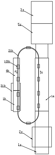
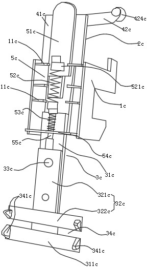
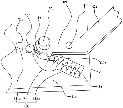
[0029] like Figure 1-Figure 13 As shown, a fully automatic electroplating equipment includes an automatic feeding device 1z for conveying electroplated workpieces, a pretreatment device 2z for cleaning electroplated workpieces, an electroplating box 1a, a ring guide rail 21b, an electroplating fixture 100c, a fixture deplating device, A cleaning device 5z for rinsing the electroplated workpiece and a discharge processing device 3z for air-drying the electroplated workpiece.

[0030] The pretreatment device 2z is arranged on the top of the automatic feeder 1z and is positioned at the middle position of the automatic feeder 1z, and the electroplating box 1a is arranged on one side of the automatic feeder 1z and is positioned at the rear side on the process direction of the pretreatment device 2z, The cleaning device 5z is arranged on th...


PUM


Abstract

The invention provides full-automatic electroplating equipment. The full-automatic electroplating equipment comprises an automatic feeding device, a pretreatment device used for cleaning electroplated workpieces, an electroplating box, an annular guide rail, an electroplating clamp, a clamp deplating device, a cleaning device used for flushing the electroplated workpieces and a discharging treatment device used for air-drying the electroplated workpieces. The pretreatment device is arranged above the automatic feeding device and located in the middle of the automatic feeding device, the electroplating box is arranged on one side of the automatic feeding device and located on the rear side of the pretreatment device in the process direction, and the cleaning device is arranged on the side, away from the automatic feeding device, of the electroplating box. The annular guide rail is arranged between the automatic feeding device and the cleaning and air-drying device and located on one side of the electroplating box. The clamp deplating device is arranged on the other side, opposite to the electroplating box, of the annular guide rail; the discharging treatment device is arranged on the side, away from the electroplating box, of the cleaning device. The electroplating device has the advantages of full automation of electroplating production, convenience in replacement of copper balls in the titanium basket and good electroplating effect.

Description

technical field [0001] The invention relates to the technical field of electroplating equipment, in particular to a fully automatic electroplating equipment. Background technique [0002] Electroplating is the process of plating a thin layer of other metals or alloys on the surface of certain metals using the principle of electrolysis. Improve wear resistance, electrical conductivity, reflectivity, corrosion resistance and enhance aesthetics. [0003] In order to overcome the defects of aluminum alloy surface hardness, wear resistance, etc., expand the application range, and prolong the service life, surface treatment technology has become an indispensable change in the use of aluminum alloys, and anodic oxidation technology is currently the most widely used and most successful. of. The anodizing device includes a fixture for fixing the anodized aluminum plate, which is connected to the power supply through a conductive device; the existing conductive device is generally f...

Claims


Application Information

Patent Timeline
IPC IPC(8): C25D17/06C25D5/08C25D5/48C25D21/08C25F5/00C25D5/34
CPCC25D17/06C25D5/08C25D5/48C25D21/08C25F5/00C25D5/34Y02P10/20
Inventor 莫恒莫凡
Owner 广东科杰电路板设备有限公司
Learn More