Polarization control device and method based on film lithium niobate
A polarization control, lithium niobate technology, applied in the field of optical communication, can solve the problems of high driving voltage, limited application, bulky volume, etc., and achieve the effect of low driving voltage, low optical loss, and fast polarization tracking
- Summary
- Abstract
- Description
- Claims
- Application Information
AI Technical Summary
Problems solved by technology
Method used
Image
Examples
Embodiment 1
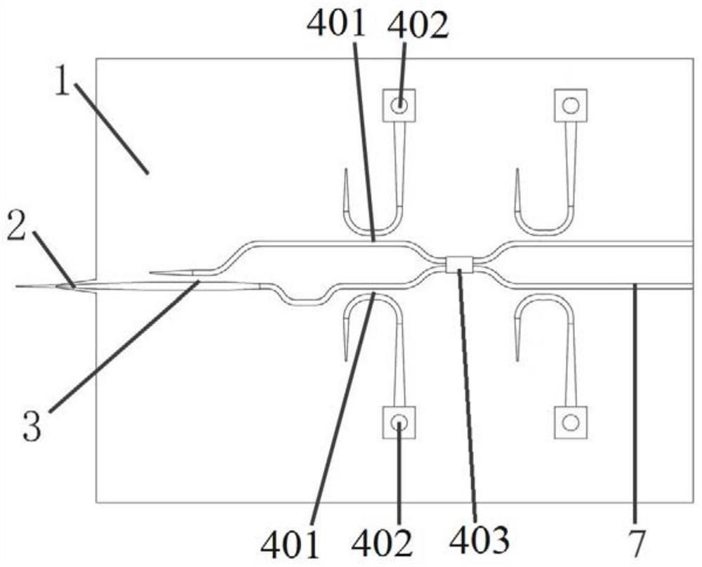
[0035] This embodiment proposes a polarization control device based on thin-film lithium niobate, such as figure 1 As shown, a schematic structural diagram of the polarization control device based on thin-film lithium niobate of the present embodiment.
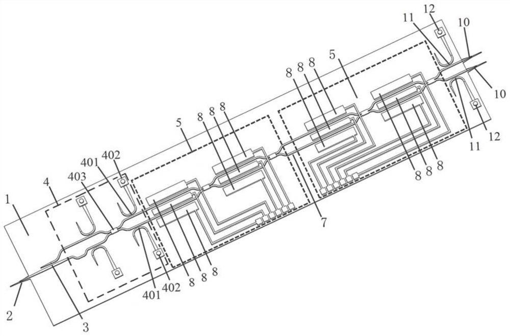
[0036] The polarization control device based on thin-film lithium niobate proposed in this embodiment includes a first optical coupler 2 , a first polarization beam splitter rotator 3 , a polarization measurement component 4 , and a 2×2 device arranged on the lithium niobate film 1 . Mach-Zehnder interferometer 5 , polarization control system 6 and lithium niobate optical waveguide 7 .
[0037] The first optical coupler 2 in this embodiment is a polarization-independent end-face coupler, which is used to couple any input polarized light into the lithium niobate optical waveguide 7 for transmission.
[0038] The first polarization beam splitter rotator 3 in this embodiment is used to convert any input polarized light into TE p...
Embodiment 2
[0048] This embodiment makes improvements on the basis of a polarization control device based on thin-film lithium niobate proposed in Example 1.
[0049] The polarization control device based on thin-film lithium niobate proposed in this embodiment includes a first optical coupler 2 , a first polarization beam splitter rotator 3 , a polarization measurement component 4 , and a 2×2 device arranged on the lithium niobate film 1 . Mach-Zehnder interferometer 5 , polarization control system 6 and lithium niobate optical waveguide 7 .
[0050] Further, the polarization measurement component 4 in this embodiment includes a first beam splitter 401 for detecting the energy of the TE polarized light in the lithium niobate waveguide, and a first photodetector 402 for monitoring the polarization state of the TE polarized light, and a 2×2 multi-mode interferometer 403; wherein, the first photodetector 402 is flip-chip welded above the output grating of the first beam splitter 401, or, th...
Embodiment 3
[0059] This embodiment makes improvements on the basis of the polarization control device based on thin-film lithium niobate proposed in embodiment 1 or 2.
[0060] The polarization control device based on thin-film lithium niobate proposed in this embodiment includes a first optical coupler 2 , a first polarization beam splitter rotator 3 , a polarization measurement component 4 , and a 2×2 device arranged on the lithium niobate film 1 . Mach-Zehnder interferometer 5 , polarization control system 6 and lithium niobate optical waveguide 7 .
[0061] Metal electrodes 8 are respectively disposed between the phase-shifting arms of the 2×2 Mach-Zehnder interferometer 5 in this embodiment and on both sides of the phase-shifting arms, and the metal electrodes 8 are connected to the polarization control system 6 through metal leads. . The polarization control system 6 controls the voltage of the metal electrode 8 through the metal lead, so as to control the distribution of the trans...
PUM
 Abstract
Description
Claims
Application Information
 - R&D
- Intellectual Property
- Life Sciences
- Materials
- Tech Scout
- Unparalleled Data Quality
- Higher Quality Content
- 60% Fewer Hallucinations
Browse by: Latest US Patents, China's latest patents, Technical Efficacy Thesaurus, Application Domain, Technology Topic, Popular Technical Reports.
© 2025 PatSnap. All rights reserved.Legal|Privacy policy|Modern Slavery Act Transparency Statement|Sitemap|About US| Contact US: help@patsnap.com


