
Underground water in-situ remediation device and method for enlarging seepage path

An in-situ remediation and groundwater technology, applied in the direction of contaminated groundwater/leachate treatment, chemical instruments and methods, restoration of contaminated soil, etc., can solve the problem of difficult control of the contact reaction time between water and repair materials, difficult construction, Dealing with issues such as unsatisfactory results

Pending Publication Date: 2022-05-24
WATER RESOURCES RES INST OF SHANDONG PROVINCE
View PDF13 Cites 0 Cited by
  • Summary
  • Abstract
  • Description
  • Claims
  • Application Information

AI Technical Summary

Problems solved by technology

[0003] Traditional groundwater in-situ remediation devices generally adopt a diaphragm wall structure (a continuous active infiltration wall is installed in the area where the groundwater flows to ensure that the groundwater in the polluted area can be treated and repaired). The maximum construction excavation depth shall not exceed 10m, and the phenomenon of aquifer collapse is likely to occur during the construction process, making the construction difficult, and it is difficult to achieve layered installation during the installation process
[0004] The in-situ treatment technology of groundwater has an insurmountable technical problem in actual engineering: it is difficult to control the contact reaction time between the water body and the repair material. In engineering, the thickness of the continuous wall is generally changed to increase the water passage. However, when the groundwater depth is deep, the construction is very difficult. When the pumping volume is large, the reaction time of the water body in the removal of materials is still very short, and the treatment effect cannot reach the expected goal.

Method used


Image

  • Underground water in-situ remediation device and method for enlarging seepage path

Examples


Embodiment Construction

[0049] The present disclosure will be further described in detail below in conjunction with the accompanying drawings and embodiments. It should be understood that the specific embodiments described herein are only used to explain the related content, but not to limit the present disclosure. In addition, it should be noted that, for the convenience of description, only the parts related to the present disclosure are shown in the drawings.

[0050] It should be noted that the embodiments of the present disclosure and the features of the embodiments may be combined with each other unless there is conflict. The technical solutions of the present disclosure will be described in detail below with reference to the accompanying drawings and in conjunction with the embodiments.

[0051] Unless otherwise stated, the illustrated exemplary embodiments / embodiments are to be understood as exemplary features providing various details of some ways in which the technical concept of the prese...


PUM


Abstract

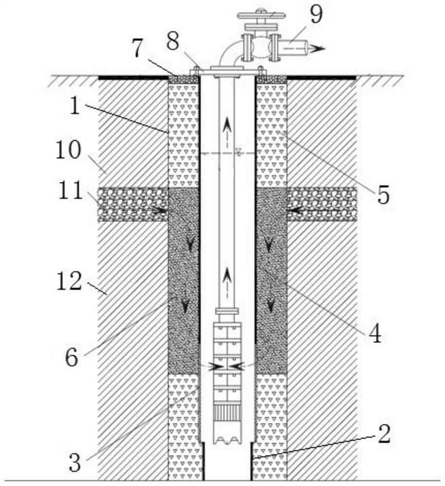
The invention provides an underground water in-situ remediation device capable of enlarging a seepage path. The underground water in-situ remediation device comprises an outer wall pipe, a lower solid wall pipe, a water filtering pipe and an upper solid wall pipe, wherein the space between the outer wall pipe and the lower solid wall pipe is filled with a filter material, the space between the outer wall pipe and the lower half part of the water filter pipe is filled with a filter material, the space between the outer wall pipe and the upper half part of the water filter pipe is filled with a PRWB material, and the space between the outer wall pipe and the lower half part of the upper solid wall pipe is filled with a PRWB material. And a filter material is filled between the outer wall pipe and the upper half part of the upper solid wall pipe.

Description

technical field [0001] The present disclosure relates to a groundwater in-situ repairing device and method for increasing the seepage path. Background technique [0002] Groundwater is easily polluted, and once the groundwater is polluted, it is difficult to remediate it. At present, the content of nitrate nitrogen in groundwater in some areas of northern my country exceeds the standard, which poses a threat to drinking water safety and ecological environment, and seriously affects the safety of water supply and health of the people. [0003] The traditional groundwater in-situ remediation device generally adopts a diaphragm wall structure (a continuous active infiltration wall is installed in the area where the groundwater flows to ensure that the groundwater in the polluted area can be treated and repaired). The maximum construction excavation depth is not more than 10m, and during the construction process, the collapse of the aquifer is likely to occur, and the construct...

Claims


Application Information

Patent Timeline
IPC IPC(8): C02F9/02B09C1/00C02F103/06C02F101/16
CPCC02F1/001C02F1/58B09C1/002C02F2103/06C02F2101/163C02F2301/08Y02W10/10
Inventor 陈学群管清花常雅雯田婵娟
Owner WATER RESOURCES RES INST OF SHANDONG PROVINCE
Learn More