Engine plume field speed and temperature synchronous measurement system

A velocity temperature, synchronous measurement technology, applied in fluid velocity measurement, velocity/acceleration/impact measurement, jet engine testing, etc., can solve the problems of unable to measure the total temperature, difficult to apply the engine plume field, difficult to calculate the thermal state of the engine, etc. , to improve the measurement accuracy

Active Publication Date: 2022-05-20
SHANGHAI JIAO TONG UNIV
View PDF7 Cites 0 Cited by
  • Summary
  • Abstract
  • Description
  • Claims
  • Application Information

AI Technical Summary

Problems solved by technology

It is generally believed that the thermal velocity can be as high as 3000m / s, and the commonly used methods such as hot wire anemometer or particle tracer velocity measurement are difficult to apply in the engine plume field
That is, if the speed cannot be measured, the total temperature cannot be measured, and it is difficult to calculate the thermal state of the engine

Method used


Image

  • Engine plume field speed and temperature synchronous measurement system
  • Engine plume field speed and temperature synchronous measurement system
  • Engine plume field speed and temperature synchronous measurement system

Examples


Embodiment Construction

[0035] Preferred embodiments of the present invention will be described in detail below in conjunction with the accompanying drawings, so as to better understand the purpose, features and advantages of the present invention. It should be understood that the embodiments shown in the drawings are not intended to limit the scope of the present invention, but only to illustrate the essence of the technical solutions of the present invention.

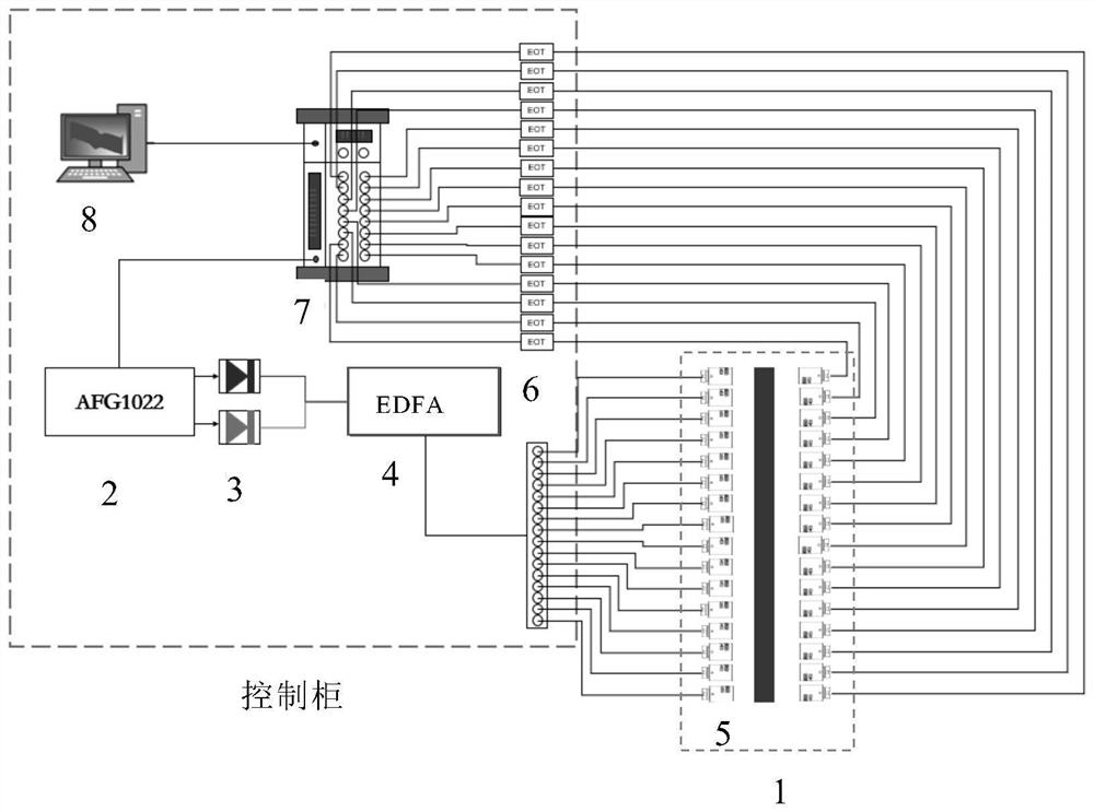
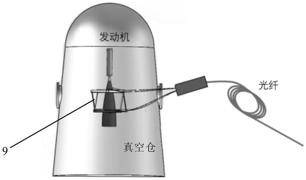
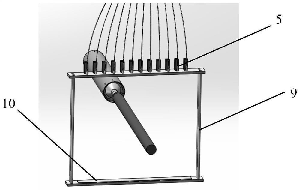
[0036] like Figure 1-3 As shown, a synchronous measurement system for velocity and temperature of an engine plume field may include a vacuum chamber 1, a signal generator 2, four lasers 3, a fiber amplifier 4, a fiber coupler 5, a photodetector 6, a data acquisition device 7 and a host 8. The vacuum chamber 1 is set at the exit of the rocket engine (ie, in the plume field). By setting a vacuum chamber, the interference of ambient air on the measurement results can be avoided. It should be understood that in some cases, the vacuum chamber...


PUM


Abstract

The invention relates to an engine plume field speed and temperature synchronous measurement system, which can comprise a signal generator, two optical fiber amplifiers, two groups of couplers, a photoelectric detector, a data acquisition device and a host, one group is used for emitting two beams of first intermediate infrared laser which are sensitive to high and low temperatures of water molecules and have different wavelengths, and the other group is used for emitting two beams of second intermediate infrared laser which are sensitive to high and low temperatures of carbon dioxide molecules and have different wavelengths; each group of optical fiber couplers is mounted at an outlet of an engine through a mounting frame, and the two mounting frames are perpendicular to each other, so that the two groups of multi-path parallel lasers are perpendicular to each other; the data acquisition device is used for acquiring photoelectric signals absorbed by gaseous molecules of an engine plume field in real time and processing the photoelectric signals into corresponding spectral data; and the host processes the spectral data through built-in spectral processing software, and synchronously obtains the speed and temperature of the engine plume field.

Description

technical field [0001] The invention relates to the technical field of engine test measurement, in particular to an engine plume field speed and temperature synchronous measurement system. Background technique [0002] The temperature of rocket engine hot test tail flame and the parameter distribution of component concentration are important indicators for evaluating the thermal performance of rocket engine. It can provide quantitative basis for rocket engine combustion state analysis, thermal protection thermal control design optimization and fault diagnosis. [0003] At present, the maximum outlet temperature of the rocket engine is 3200°C. During the test, the temperature measurement methods are mainly thermocouple and infrared thermal imager. Among them, the thermocouple mode has limitations in temperature upper limit, dynamic response, and accuracy. With the continuous improvement of the upper limit requirements of high temperature measurement, and the requirement of ...

Claims


Application Information

Patent Timeline
Patent Type & Authority Applications(China)
IPC IPC(8): G01M15/14G01P5/00G01K11/00
CPCG01M15/14G01P5/00G01K11/006G01P5/26G01P5/001
Inventor 刘训臣
Owner SHANGHAI JIAO TONG UNIV
Why Eureka
Try Eureka