Micro-nano flow fluorescent bleaching speed measurement method and system based on camera imaging

A fluorescence bleaching and camera imaging technology, applied in fluid velocity measurement, optics, microscopy, etc., can solve the problems of unfavorable stability of structure optimization measurement, inability to distinguish fluid velocity direction, and limited application range, and achieve simple structure and simple operation. , the effect of overcoming limitations

Active Publication Date: 2021-08-24
NORTHWEST UNIV(CN)
View PDF9 Cites 0 Cited by
  • Summary
  • Abstract
  • Description
  • Claims
  • Application Information

AI Technical Summary

Problems solved by technology

[0003] However, the traditional LIFPA technology can only measure the magnitude of the fluid velocity at a single position, and cannot distinguish the direction of the fluid velocity, which is a significant defect for the fluid velocity measurement technology
Even in the improved LIFPA technology, for example: the LIFPA technology based on optical fiber bundle can realize the measurement of fluid velocity direction, but the structure of the device is complex, requiring the same set of measurement subsystems (single A set of measurement subsystems includes: high-sensitivity photomultiplier tube, signal amplification and filtering devices, etc.), and the position of the fiber bundle needs to be adjusted before use, so that the receiving end of the fiber bundle is always aligned with the fluorescence center in the static flow field, and The fluorescent spot is required to form a strict Gaussian distribution
This is unfavorable for the structural optimization of the experimental device, the actual operation of the experimental process, and the stability of the measurement.
More importantly, LIFPA technology based on optical fiber bundles is still a single-point measurement technology, which limits the application range of this technology

Method used


Image

  • Micro-nano flow fluorescent bleaching speed measurement method and system based on camera imaging
  • Micro-nano flow fluorescent bleaching speed measurement method and system based on camera imaging
  • Micro-nano flow fluorescent bleaching speed measurement method and system based on camera imaging

Examples


Embodiment Construction

[0054] The following will clearly and completely describe the technical solutions in the embodiments of the present invention with reference to the accompanying drawings in the embodiments of the present invention. Obviously, the described embodiments are only some, not all, embodiments of the present invention. Based on the embodiments of the present invention, all other embodiments obtained by persons of ordinary skill in the art without making creative efforts belong to the protection scope of the present invention.

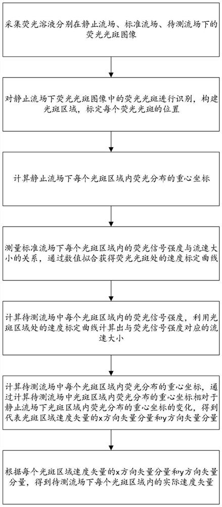
[0055] The embodiment of the present invention discloses a method and system for measuring the speed of micro-nano flow fluorescence bleaching based on camera imaging, and the principle of speed measurement used is:

[0056] Utilizing the characteristic that the fluorescence intensity increases with the increase of the flow velocity, and calculating the intensity of the fluorescence signal collected by the camera according to the algorithm, the velocity of the ...


PUM


Abstract

The invention discloses a micro-nano flow fluorescent bleaching speed measurement method and system based on camera imaging, which are applied to the technical field of micro-nano flow field speed measurement. The method comprises the following steps: collecting fluorescent spot images of a fluorescent solution in a static flow field, a standard flow field and a to-be-measured flow field; carrying out light spot identification in a static flow field, and constructing a light spot area; measuring the relationship between the fluorescence signal intensity and the flow velocity in the region under a standard flow field to obtain a velocity calibration curve; calculating the fluorescence signal intensity in the area in the flow field to be measured, and calculating the corresponding flow velocity by using the velocity calibration curve; and obtaining the x-direction vector component and the y-direction vector component of the velocity vector in the region by calculating the change of the barycentric coordinates of the fluorescence distribution in the region in the flow field to be measured relative to the barycentric coordinates of the fluorescence distribution in the region in the static flow field, and then, obtaining the velocity vector of the light spot region. The system is simple in structure, can measure the fluid velocity and direction at the same time, supports multi-point measurement, and is high in precision and easy to operate.

Description

technical field [0001] The invention relates to the technical field of micro-nano flow field velocity measurement, and more specifically relates to a method and system for measuring the velocity of micro-nano flow fluorescence bleaching based on camera imaging. Background technique [0002] Fluorescence bleaching velocimetry technology is a new type of micro-nano flow field velocity measurement technology. At present, the most commonly used traditional fluorescence bleaching velocimetry technology is Laser Induced Fluorescence Photobleaching Anemometer (LIFPA) technology, which is mainly used in micro-nano flow control. The chip design and the research on the mechanism of micro-nano fluid dynamics can realize the measurement of the velocity of the micro-nano flow field with high temporal and spatial resolution. The advantage of LIFPA technology is that it can simultaneously achieve a spatial resolution of tens to hundreds of nm and a time resolution of up to 3 μs, which is d...

Claims


Application Information

Patent Timeline
Patent Type & Authority Applications(China)
IPC IPC(8): G01P5/26G01P13/02G01P1/00G02B21/00
CPCG01P5/26G01P13/02G01P1/00G02B21/0076
Inventor 赵伟陈玉
Owner NORTHWEST UNIV(CN)
Why Eureka
Try Eureka