Tower foot workpiece automatic welding system and method based on weld joint recognition

An automatic welding and workpiece technology, applied in welding equipment, auxiliary welding equipment, welding/cutting auxiliary equipment, etc., can solve the problems of low overall productivity, high labor intensity of workers, and waiting for development, so as to improve welding accuracy and obtain simple methods , The effect of improving welding efficiency

Active Publication Date: 2022-05-20
ZHEJIANG UNIV
View PDF7 Cites 2 Cited by
  • Summary
  • Abstract
  • Description
  • Claims
  • Application Information

AI Technical Summary

Problems solved by technology

However, such methods are mostly used for planar workpieces, and are not suitable for three-dimensional tower feet with complex structures.
[0005] It can be seen that the current tower foot welding processing method has the following limitations: 1) The product size is customized, the welding process of the tower foot still relies on manual welding, the labor intensity of the workers is high, and the overall productivity is low; It needs to be developed and cannot solve the problem of welding seam identification of small batches and multiple varieties of three-dimensional workpieces; 3) The working environment of tower foot welding is harsh, and the waste gas and dust generated during the welding process seriously endanger the health of welders

Method used


Image

  • Tower foot workpiece automatic welding system and method based on weld joint recognition
  • Tower foot workpiece automatic welding system and method based on weld joint recognition
  • Tower foot workpiece automatic welding system and method based on weld joint recognition

Examples


Embodiment Construction

[0033] The present invention will be further described in detail below with reference to the accompanying drawings and embodiments. It should be noted that the following embodiments are intended to facilitate the understanding of the present invention, but do not limit it in any way.

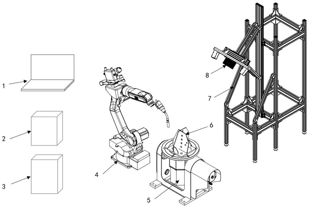
[0034] Such as figure 1 As shown, an automatic welding system for tower foot workpieces based on weld seam recognition includes: host computer 1, welding power supply 2, robot control cabinet 3, welding robot 4, two-axis positioner 5, welding workpiece 6, and scanning frame 7 and a 3D structured light camera8.

[0035] The host computer 1 is used to receive point cloud information of the workpiece surface captured by the three-dimensional structured light camera 8, perform point cloud stitching and workpiece surface reconstruction, and complete weld seam extraction and welding path planning of the welding robot 4. The welding power source 2 provides power for the robot control cabinet 3, the we...


PUM


Abstract

The invention discloses a tower foot workpiece automatic welding system and method based on weld joint recognition, and the system comprises an upper computer, a robot control cabinet, a welding robot, a two-axis positioner and a three-dimensional structured light camera which are matched with one another; the upper computer is used for receiving the workpiece surface point cloud information shot by the three-dimensional structured light camera, performing point cloud splicing and workpiece surface reconstruction, and completing weld joint extraction and welding path planning of the welding robot; the robot control cabinet is used for controlling welding of the welding robot and movement of the two-axis positioner. The two-shaft positioner is used for fixing a welding workpiece and adjusting the angle of the welding workpiece; and the three-dimensional structured light camera is used for shooting surface point cloud information of the welding workpiece. By utilizing the method, the welding path planning of the welding robot can be directly guided by extracting the three-dimensional coordinate information of all the welding seams of the welding part of the welding workpiece, the welding efficiency and the welding precision of the tower foot workpiece can be improved, and the method has universality for tower foot workpieces of different specifications.

Description

technical field [0001] The invention belongs to the field of automatic welding of robots, and in particular relates to an automatic welding system and method for tower foot workpieces based on welding seam identification. Background technique [0002] The power angle steel tower is a tower-shaped building for power transmission, which belongs to the space truss structure. The tower foot of the power angle steel tower is a steel plate weldment, which generally needs to be customized according to factors such as terrain and angle steel tower structure. The production process of the tower foot is as follows: 1) Personalized design of the shape and size of the tower foot; 2) Cutting the steel plate according to the drawing to complete the blanking of the steel plate; 3) Manual spot welding of the steel plate according to the drawing to realize the preliminary connection between the steel plate and the steel plate; 4) Overall Arc welding, to complete the welding operation of all...

Claims


Application Information

Patent Timeline
Patent Type & Authority Applications(China)
IPC IPC(8): B23K37/02B23K37/047B25J9/16B25J13/06
CPCB23K37/02B23K37/047B25J11/005B25J9/1664B25J13/06
Inventor 梁文龙傅建中徐月同王郑拓徐冠华姚鑫骅
Owner ZHEJIANG UNIV
Why Eureka
Try Eureka