Modern sponge city construction green roof structure based on architectural design engineering

A technology of sponge city and architectural design, applied in building structure, supporting structure of photovoltaic modules, buildings, etc., can solve problems such as affecting the effect of rainwater collection, unreasonable use of sunlight and rainwater resources, and waste of rainwater resources, etc. Improves cleanliness and surface transmittance, improves energy harvesting, and avoids wet damage

Inactive Publication Date: 2022-05-17
石哲
View PDF0 Cites 0 Cited by
  • Summary
  • Abstract
  • Description
  • Claims
  • Application Information

AI Technical Summary

Problems solved by technology

[0003] However, the existing building roof structure design is relatively traditional, mostly covered with waterproof membranes, supplemented by planting green plants to improve the temperature, the green plants only use a small amount of rainwater resources, which is not fully utilized, and the green plants Falling dead branches affect the effect of rainwater collection, not only easy to block, but also easy to cause rainwater to silt up and spread to the roof, resulting in waste of rainwater resources. In addition, green plants only contribute to a limited cooling effect of the house, and do not make reasonable use of the roof opening Sunshine resources and rainwater resources, it is urgent to propose a green roof structure based on architectural design engineering for modern sponge city construction

Method used


Image

  • Modern sponge city construction green roof structure based on architectural design engineering
  • Modern sponge city construction green roof structure based on architectural design engineering
  • Modern sponge city construction green roof structure based on architectural design engineering

Examples


Embodiment Construction

[0030] In order to make the technical means, creative features, goals and effects achieved by the present invention easy to understand, the present invention will be further described below in conjunction with specific embodiments.

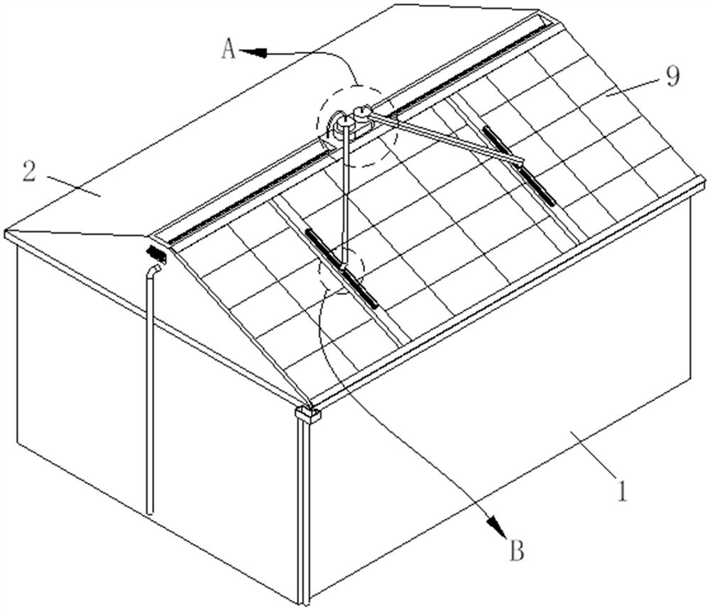
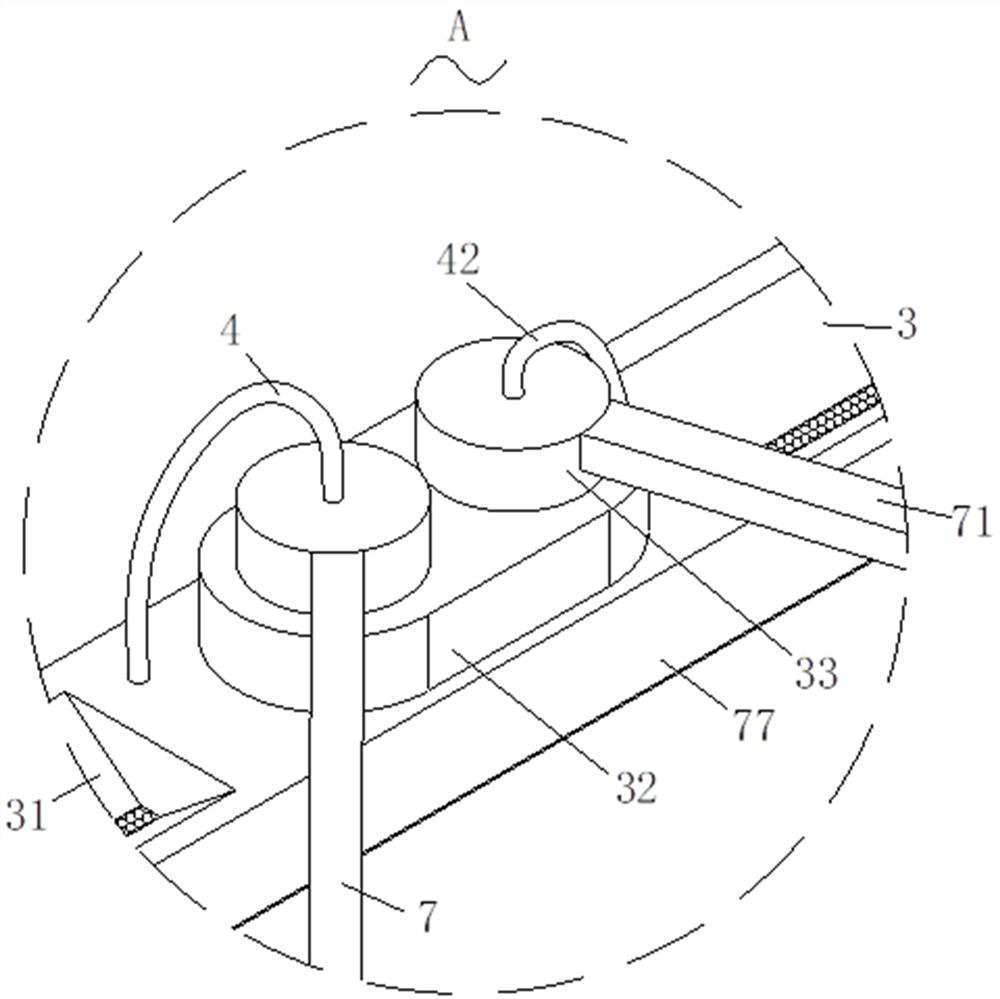
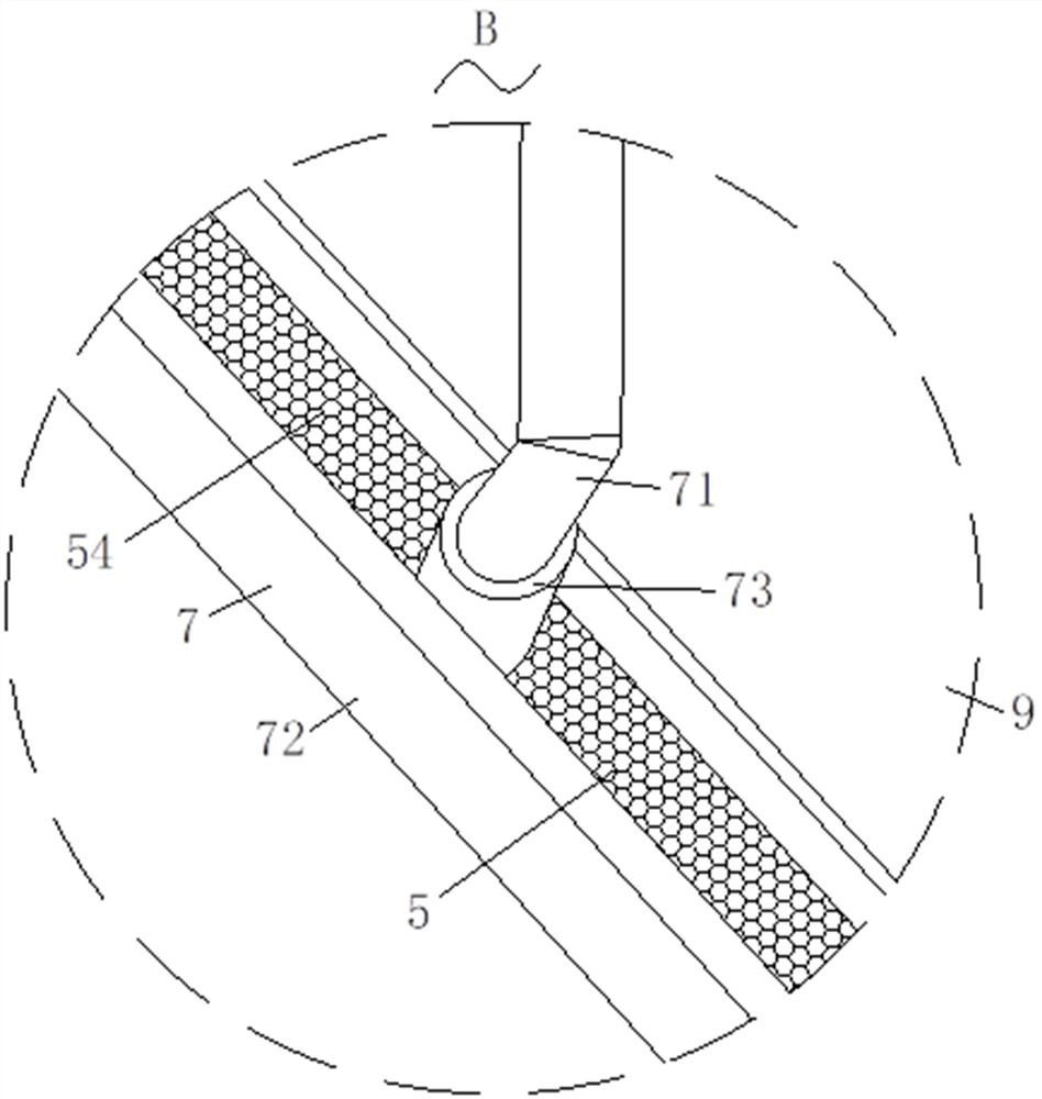
[0031] like Figure 1-Figure 10 As shown, a kind of modern sponge city construction green roof structure based on architectural design engineering according to the present invention includes a house body 1, a roof 2 is provided on the top of the house body 1, and a solar panel is installed on the top of the roof 2 9. The top of the roof 2 is provided with a deflection mechanism 3, the deflection mechanism 3 is provided with a liquid supply mechanism 4, and the bottom end of the liquid supply mechanism 4 is provided with a slag removal mechanism 5 and a decontamination mechanism 6. A cleaning mechanism 7 is provided on the top of the solar panel 9 , and a reciprocating mechanism 8 is arranged inside the cleaning mechanism 7 .

[0032] Specifically...


PUM


Abstract

The invention relates to the technical field of green buildings, in particular to a modern sponge city construction green roof structure based on architectural design engineering, which comprises a room body, a roof is arranged at the top end of the room body, a solar panel is mounted at the top end of the roof, a deflection mechanism is arranged at the top end of the roof, and a liquid supply mechanism is arranged on the deflection mechanism. A slag removal mechanism and a dirt removal mechanism are arranged at the bottom end of the liquid supply mechanism, a cleaning mechanism is arranged at the top end of the solar panel, and a reciprocating mechanism is arranged in the cleaning mechanism; through the deflection mechanism and the liquid supply mechanism, the cleaning mechanism and the liquid supply mechanism can be conveniently driven at the same time, water resources are better utilized, and the energy collection effect is improved; impurities can be conveniently removed through the slag removal mechanism, and the influence on the quality of recycled water resources is avoided; sludge and the like settled at the bottom of the pool can be conveniently and automatically cleaned through the decontamination mechanism; and through the cleaning mechanism and the reciprocating mechanism, the solar panel can be cleaned in a reciprocating manner, the cleanliness and the surface light transmittance of the solar panel are improved, and green energy is generated more efficiently.

Description

technical field [0001] The invention relates to the technical field of green buildings, in particular to a green roof structure for modern sponge city construction based on architectural design engineering. Background technique [0002] Sponge city is a new generation of urban stormwater management concept, which means that the city can be like a sponge, which has good flexibility in adapting to environmental changes and responding to natural disasters caused by rainwater, and releases and utilizes the stored water when needed , to realize the free migration of rainwater in the city; in order to cooperate with the proposed concept, the existing buildings have developed green building technologies that conform to the concept of sponge city, especially the technology used in the field of roof structures. [0003] However, the existing building roof structure design is relatively traditional, mostly covered with waterproof membranes, supplemented by planting green plants to i...

Claims


Application Information

Patent Timeline
Patent Type & Authority Applications(China)
IPC IPC(8): E04D13/18E03B3/02H02S20/23H02S40/10B08B1/00B08B3/04
CPCE04D13/00E03B3/02H02S20/23H02S40/10B08B1/008B08B3/04Y02E10/50Y02A20/108
Inventor 石哲王倍王勇
Owner 石哲
Why Eureka
Try Eureka