Expanded graphite plate lossless cutting device and using method thereof
A technology of expanding graphite and cutting, which is applied in the field of non-destructive cutting devices for expanded graphite plates. It can solve the problems of increased density, broken expanded graphite plates, and easy compression, etc., so as to improve the service life, increase the yield, and reduce the impact. Effect
- Summary
- Abstract
- Description
- Claims
- Application Information
AI Technical Summary
Problems solved by technology
Method used
Image
Examples
Embodiment 1
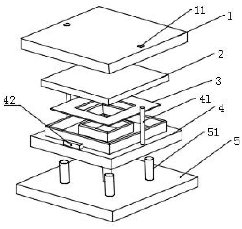
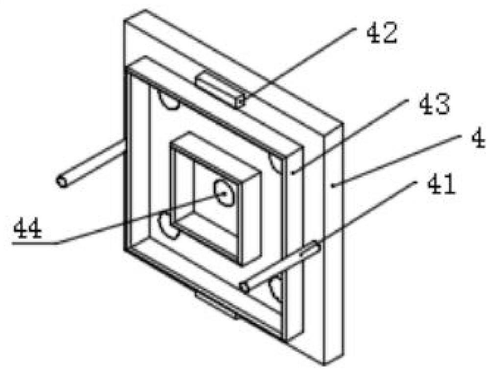
[0045] A non-destructive cutting device for expanded graphite plates, comprising a cover plate, a knife mold and a discharge plate, the side of the knife mold facing the cover plate is provided with a cutting portion enclosed by a knife edge, and the discharge plate is sleeved on the enclosure Inside.
[0046] The enclosure includes an inner enclosure and an outer enclosure, and the inner enclosure is located within the outer enclosure;
[0047] The projection of the discharge plate on the upper surface of the die is located between the inner enclosure and the outer enclosure.
[0048] Positioning pins are provided on the upper surface of the die cutter, and positioning holes are provided on the cover plate opposite to the positioning pins.
[0049] A limiting block is arranged on the upper surface of the mold, and the limiting block is located on the edge of the cutting mold and does not overlap with the position of the positioning pin.
[0050] The die is also provided with ...
Embodiment 2
[0061] A non-destructive cutting device for expanded graphite plates, the same as embodiment one will not be repeated; wherein
[0062] The blade has a thickness of 0.4mm and a height of 4mm; the blade is a double-edged knife;
[0063] Described cutting die is engraving die, and the thickness of described cutting die is 30mm;
[0064] The height of the limiting block is 6mm;
[0065] The minimum distance between the maximum radius tangent of the discharge hole and the cutting edge is greater than 2mm.
[0066] The flatness of the ejector plate is 1mm, and the parallelism is 1mm;
[0067] The height of the discharge ejector pin is 40 mm, and the maximum diameter is 1 mm smaller than the diameter of the discharge hole.
[0068] The thickness of the cover plate is 40mm, the flatness is 1mm, the parallelism is 1mm, and the material is aluminum alloy, stainless steel.
[0069] The thickness of the discharge plate is 1mm, the flatness is 1mm, the parallelism is 1mm, and the mate...
Embodiment 3
[0071] A method for using the expanded graphite plate non-destructive cutting device described in Embodiment 1 or Embodiment 2, comprising
[0072] Feeding, assembling the cover plate, cutting die and discharge plate into a cutting structure, the cutting die and cover plate are positioned and installed through positioning pins and positioning holes, and the discharge plate is installed between the inner enclosure and the outer enclosure , and fix the cutting part, place the expanded graphite plate between the cutting part and the cover plate; the minimum frame of the expanded graphite plate should be more than 2mm larger than the maximum edge of the outer encirclement, pass the cover plate through the positioning hole along the positioning pin of the die The self-weight is flatly pressed on the top of the expanded graphite plate to achieve material fixation.
[0073] Stamping and cutting, extruding the cover plate with a pressure of 2.5 tons, and stamping and cutting the expan...
PUM
| Property | Measurement | Unit |
|---|---|---|
| thickness | aaaaa | aaaaa |
| height | aaaaa | aaaaa |
| thickness | aaaaa | aaaaa |
Abstract
Description
Claims
Application Information
 - R&D Engineer
- R&D Manager
- IP Professional
- Industry Leading Data Capabilities
- Powerful AI technology
- Patent DNA Extraction
Browse by: Latest US Patents, China's latest patents, Technical Efficacy Thesaurus, Application Domain, Technology Topic, Popular Technical Reports.
© 2024 PatSnap. All rights reserved.Legal|Privacy policy|Modern Slavery Act Transparency Statement|Sitemap|About US| Contact US: help@patsnap.com


