Energy-saving non-negative pressure water supply equipment
A water supply equipment, non-negative pressure technology, applied in the direction of water supply equipment, water supply main pipeline, water supply pipeline system, etc., can solve the problems affecting work efficiency and so on
- Summary
- Abstract
- Description
- Claims
- Application Information
AI Technical Summary
Problems solved by technology
Method used
Image

Examples
Embodiment 1
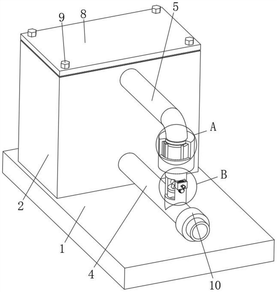
[0033] Example 1: an energy-saving type non-negative pressure water supply equipment, comprising a base plate 1 and a control unit 7;
[0034] Bottom plate 1: the upper side of the rear end is provided with a water storage tank 2, the rear side of the storage tank 2 is provided with an inlet pipe 3 connected with the internal, the interior of the storage tank 2 is provided with a water outlet pipe 4 through the pump, and the water outlet pipe 4 passes out of the front side of the storage tank 2, the front and upper end of the storage tank 2 is provided with a purification pipe 5, and the front end of the purification pipe 5 is connected with the interior of the outlet pipe 4, and the middle of the purification pipe 5 is provided with a purification unit 6;
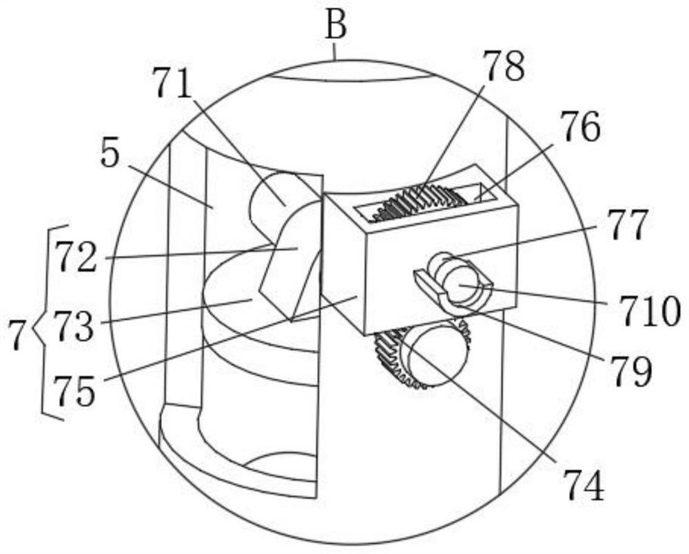
[0035]Control unit 7: comprising a moving axis 71, a fixed block 72, a butterfly plate 73 and a power component, the front and rear sides of the activity axis 71 are respectively connected with the inner front and rear side...
Embodiment 2
[0042] The difference between the present embodiment and Example 1 is:
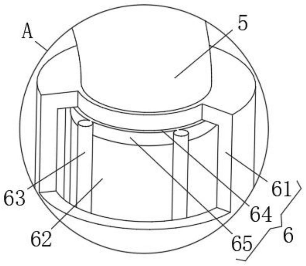
[0043] In the present embodiment, the purification unit 6 comprises a purification cylinder 61, a transparent cylinder 62 and a ultraviolet sterilization lamp 63, the middle of the purification tube 5 is provided with a purification cylinder 61, the interior of the purification cylinder 61 is provided with a transparent cylinder 62, the inside of the purification cylinder 61 and the outer side of the transparent cylinder 62 form a closed space, the interior of the confined space is evenly arranged along the circumferential direction with no less than three ultraviolet germicidal lamps 63.
[0044] Under the action of forming a confined space between the inside of the purification cylinder 61 and the outer side of the transparent cylinder 62, the protection of the ultraviolet germicidal lamp 63 is realized, and the water inside the purification cylinder 61 is entered through the purification tube 5, and the role...
Embodiment 3
[0048] The difference between the present embodiment and Example 1 is:
[0049] In the present embodiment, further comprising a cover body 8 and a bolt 9, the upper end of the reservoir 2 is provided with a cover body 8, the cover body 8 is connected by a bolt 9 and the upper end of the reservoir 2.
[0050] Under the action of the cover body 8, the role of disassembly cleaning of the interior of the storage tank 2 can be realized, and the cover body 8 can be removed under the action of bolt 9.
[0051] Further comprising a valve 10, the outer front end of the outlet pipe 4 is provided with a valve 10, the valve 10 is located in front of the connection between the purification pipe 5 and the outlet pipe 4. Under the action of valve 10, the opening and closing effect of the front end of the purification tube 5 is controlled.
[0052] At the time of use:
[0053]Through the inlet pipe 3 to achieve the role of water supply inside the storage tank 2, under the action of the pump pump...
PUM
 Abstract
Description
Claims
Application Information
 - R&D
- Intellectual Property
- Life Sciences
- Materials
- Tech Scout
- Unparalleled Data Quality
- Higher Quality Content
- 60% Fewer Hallucinations
Browse by: Latest US Patents, China's latest patents, Technical Efficacy Thesaurus, Application Domain, Technology Topic, Popular Technical Reports.
© 2025 PatSnap. All rights reserved.Legal|Privacy policy|Modern Slavery Act Transparency Statement|Sitemap|About US| Contact US: help@patsnap.com