System and method for increasing yield of low-carbon olefins
A technology for low-carbon olefins and carbon tetra-olefins, which is applied in chemical instruments and methods, hydrocarbon purification/separation, processing of hydrocarbon oils, etc. Improve comprehensive competitiveness and economic benefits, and promote the effect of application value
- Summary
- Abstract
- Description
- Claims
- Application Information
AI Technical Summary
Problems solved by technology
Method used
Image
Examples
Embodiment 1
[0063] This example is used to illustrate the system and method for increasing the production of light olefins of the present invention.
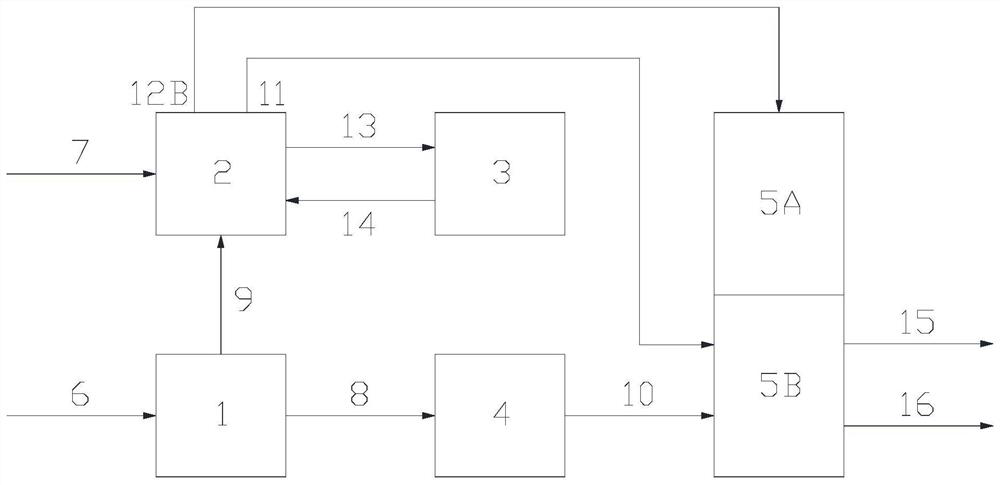
[0064] like figure 1 As shown, the system includes: extraction unit 1, hydrogenation separation unit 2, normalization unit 3, olefin catalytic cracking unit 4, ethylene plant cracking unit 5A and ethylene plant separation unit 5B; unsaturated C4 raw material feed The pipeline is connected with the extraction unit 1; the saturated carbon four raw material feed line is connected with the hydrogenation separation unit 2; the extraction unit 1 is connected with the hydrogenation separation unit through the extraction unit C4 alkane discharge pipeline 2 are connected; the extraction unit 1 is connected with the olefin catalytic cracking unit 4 through the extraction unit carbon tetraolefin discharge pipeline; the hydrogenation separation unit 2 is connected with the normalization unit through the isobutane-rich discharge pipeline Unit 3 is con...
comparative approach 1-2
[0075] Since the rich olefin C4 cannot directly enter into ethylene cracking (causing coking), it can only be burned as fuel. Therefore, comparison scheme 1 is used as fuel gas, and comparison scheme 2 is for the production of high-octane alkylate oil. The comparison of income per ton is shown in Table 1 below.
[0076] Table 1 C4 income per ton of different processing schemes
[0077]
[0078] Note: Triene yield is the sum of the yields of ethylene, propylene, and butadiene.
Embodiment 2
[0080] This example is used to illustrate the system and method for increasing the production of light olefins of the present invention.
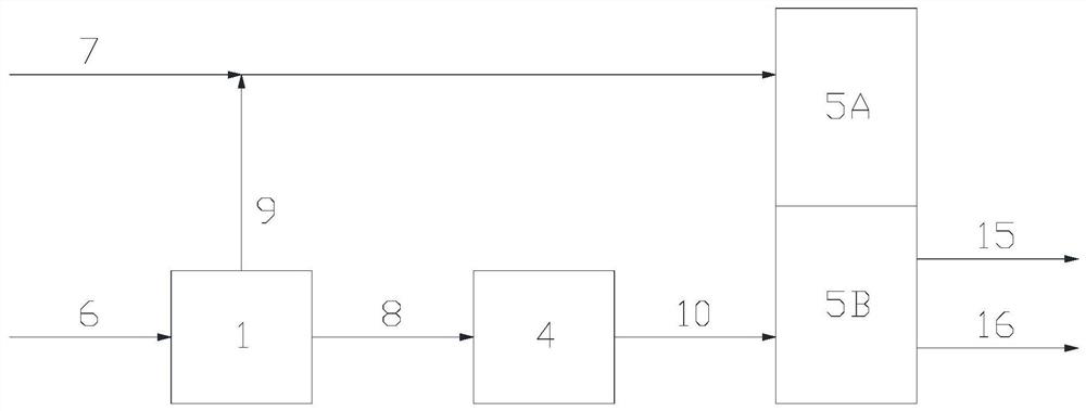
[0081] like figure 2 As shown, the system includes: extraction unit 1, hydrogenation separation unit 2, olefin catalytic cracking unit 4, ethylene plant cracking unit 5A and ethylene plant separation unit 5B; Unit 1 is connected; the saturated carbon four raw material feed line is connected with the hydrogenation separation unit 2; the extraction unit 1 is connected with the hydrogenation separation unit 2 through the extraction unit carbon four alkane discharge pipeline; the extraction The extraction unit 1 is connected to the olefin catalytic cracking unit 4 through the C4 olefin discharge pipeline of the extraction unit; the hydrogenation separation unit 2 is connected to the ethylene unit through the hydrogenation tail gas discharge pipeline and the butane-rich discharge pipeline respectively. The separation unit 5B is connected to th...
PUM
 Abstract
Description
Claims
Application Information
 - R&D
- Intellectual Property
- Life Sciences
- Materials
- Tech Scout
- Unparalleled Data Quality
- Higher Quality Content
- 60% Fewer Hallucinations
Browse by: Latest US Patents, China's latest patents, Technical Efficacy Thesaurus, Application Domain, Technology Topic, Popular Technical Reports.
© 2025 PatSnap. All rights reserved.Legal|Privacy policy|Modern Slavery Act Transparency Statement|Sitemap|About US| Contact US: help@patsnap.com


