Horizontal spray drying unit for seasoning production
A drying unit and condiment technology, applied in the direction of spray evaporation, evaporator accessories, etc., can solve the problems of unfavorable operation efficiency and use effect, powder granularity, low drying efficiency, etc., to improve drying efficiency and product quality, prevent Effect of clogging, reduction of equipment cost and operating cost
- Summary
- Abstract
- Description
- Claims
- Application Information
AI Technical Summary
Problems solved by technology
Method used
Image
Examples
Embodiment 1
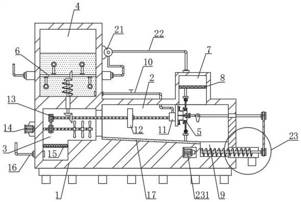
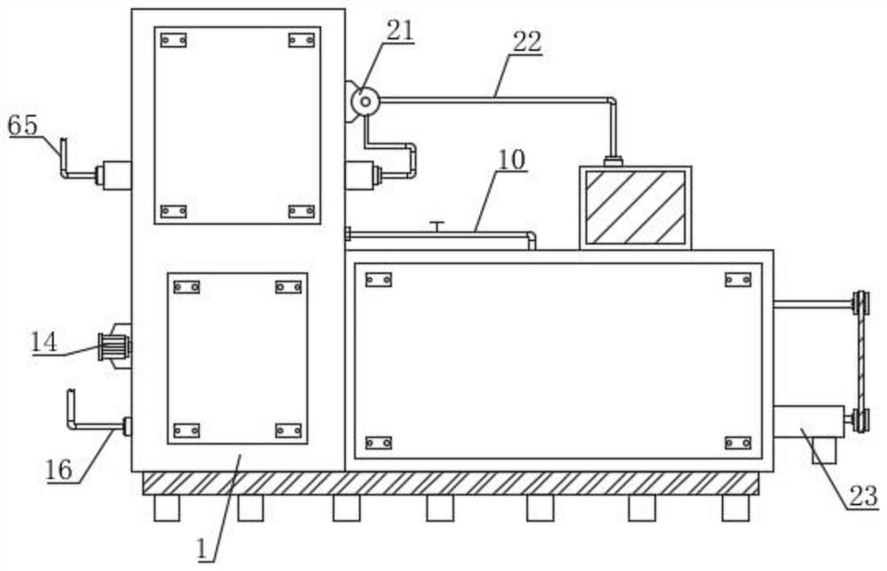
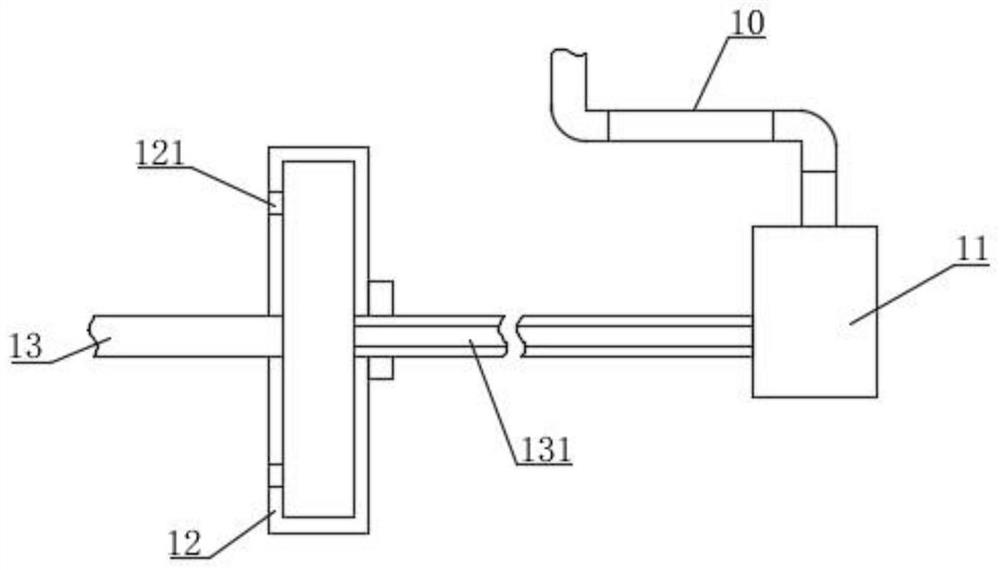
[0045] Such as Figure 1-7 As shown, a horizontal spray drying unit for condiment production proposed by the present invention comprises a drying box 1, and a spray drying chamber 2, a heating blast chamber 3, a material storage chamber 4 and a material receiving chamber are provided in the drying box 1. chamber 9, the heating blast chamber 3 communicates with the spray drying chamber 2, the material receiving chamber 9 is located below the side of the spray drying chamber 2 away from the heating blast chamber 3, and the heating blast chamber 3 is equipped with a horizontally arranged electrical appliance near the bottom. Heating net 15, the air supply pipe 16 that heating blast chamber 3 is communicated with is installed on the drying cabinet 1, and the communicating place of air supply pipe 16 and heating blast chamber 3 is positioned at the below of electric heating net 15, and air supply pipe 16 is directed to Dry and clean air is input into the heating blast chamber 3, an...
Embodiment 2
[0051] Such as figure 1 with Figure 7 As shown, the difference between this embodiment and Embodiment 1 is that a mixing and preheating component 6 for stirring and preheating the material liquid is provided in the storage chamber 4, and the mixing and preheating component 6 and the exhaust chamber 7 pass through the The air duct 22 is connected, and the return air duct 22 is provided with a fan 21, the fan 21 extracts the hot exhaust gas in the exhaust chamber 7, and the return air duct 22 transports the hot exhaust gas to the mixing and preheating assembly 6, specifically, The mixing and preheating assembly 6 includes a rotating air guiding shaft 61 and a transmission shaft 62, the rotating air guiding shaft 61 is horizontally arranged and rotatably installed in the material storage chamber 4, and the drying box 1 is fixed with a first sealing box 63 and a The second sealed box 64, the air return pipe 22 communicates with the first sealed box 63, that is, the return air pi...
Embodiment 3
[0055] Such as figure 1 with Figure 9-10 As shown, the difference between this embodiment and Embodiment 1 and Embodiment 2 is that a driving discharge assembly 23 is installed in the material receiving chamber 9, and the driving discharge assembly 23 is located at a position near the bottom of the material receiving chamber 9, and the driving discharge assembly 23 includes a discharge motor 231 and a discharge shaft 232. The side wall of the drying box 1 is fixedly equipped with a discharge pipe 235 communicating with the material receiving chamber 9, and the bottom of one end of the discharge pipe 235 away from the material receiving chamber 9 is installed with a bottom The material pipe 236, the discharge motor 231 is fixedly installed on the drying box 1 through the motor base, and the output end of the discharge motor 231 is equipped with a discharge shaft 232, and the discharge motor 231 makes the discharge shaft 232 rotate;
[0056] The discharge shaft 232 is arranged...
PUM
 Abstract
Description
Claims
Application Information
 - R&D
- Intellectual Property
- Life Sciences
- Materials
- Tech Scout
- Unparalleled Data Quality
- Higher Quality Content
- 60% Fewer Hallucinations
Browse by: Latest US Patents, China's latest patents, Technical Efficacy Thesaurus, Application Domain, Technology Topic, Popular Technical Reports.
© 2025 PatSnap. All rights reserved.Legal|Privacy policy|Modern Slavery Act Transparency Statement|Sitemap|About US| Contact US: help@patsnap.com


