
Shutdown purging method for fuel cell system

A fuel cell system and fuel cell technology, applied in the direction of fuel cells, fuel cell additives, electrolyte treatment of solid electrolyte batteries, etc., can solve the problem of affecting the purging effect, increasing the energy consumption of air compressors, increasing the use and maintenance costs, etc. problems, to achieve the effect of shortening the purging time, reducing the water production volume, and avoiding additional water production

Pending Publication Date: 2022-05-06
DONGFANG ELECTRIC (CHENGDU) HYDROGEN FUEL CELL TECH CO LTD
View PDF3 Cites 1 Cited by
  • Summary
  • Abstract
  • Description
  • Claims
  • Application Information

AI Technical Summary

Problems solved by technology

Although this plan considers the purging temperature and gas volume, it does not consider: 1. After the purging is over and the cooling water temperature is lower than 60°C, the water vapor in the battery stack will continue to condense and produce water, which will re-wet the membrane electrodes
2. Control the speed of the air compressor so that the air flow is more than 10 times the required air flow under the condition of outputting the load current. This air volume requirement is too high. While increasing the energy consumption of the air compressor, it may also be caused by the The performance limit cannot reach this volume, which will affect the purging effect
The realization of this solution needs to be combined with the internal resistance meter to monitor the AC impedance value of the fuel cell. In practical applications, each fuel cell system needs to be equipped with an additional set of AC impedance meter, which greatly increases the use and maintenance costs.
At the same time, this solution does not take into account the problem that after the purge is completed, the water vapor in the stack will condense due to the temperature drop of the battery stack, so that the membrane will become wet again, resulting in a further decrease in internal resistance.

Method used


Image

  • Shutdown purging method for fuel cell system

Examples


Embodiment Construction

[0034] Embodiments of the invention are described in detail below, examples of which are illustrated in the accompanying drawings. The embodiments described below by referring to the figures are exemplary and are intended to explain the present invention and should not be construed as limiting the present invention.

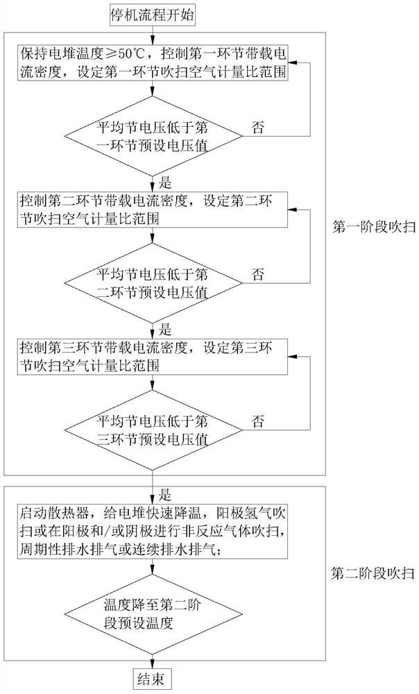
[0035] Such as figure 1 As shown, the fuel cell system shutdown purging method in this embodiment includes the following steps:

[0036] The first stage of purging: set the preset temperature of the first stage to 50°C, control the thermostat to maintain the temperature of the cooling medium at the inlet or outlet of the fuel cell at ≥ 50°C, and classify the loading current in descending order, at least A link:

[0037] For example, in the first link, the loading current density is 0.4A / cm 2 current, carry out on-load purge. When the average junction voltage drops to 0.8V, enter the second stage, and the loading current density is 0.3A / cm 2 At this time, the...


PUM


Abstract

The invention belongs to the technical field of fuel cells, and particularly relates to a shutdown purging method for a fuel cell system. According to the technical scheme, the shutdown purging method for the fuel cell system comprises the following steps: first-stage purging: setting a first-stage preset temperature, and maintaining the temperature of a cooling medium at an inlet or an outlet of a fuel cell to be greater than or equal to the first-stage preset temperature; loading current, and purging the fuel cell until the monitored voltage is less than a preset voltage value; second-stage purging: forcibly cooling the galvanic pile, and introducing gas into the galvanic pile for purging; and setting a second-stage preset temperature, and stopping cooling and purging when the temperature of the fluid medium at the inlet or the outlet of the fuel cell is lower than the second-stage preset temperature, or reaches the set purging time, or reaches the set voltage mean value or minimum value. The fuel cell system shutdown purging method provided by the invention is high in purging efficiency and prevents condensate water from remaining in an electric pile.

Description

technical field [0001] The invention belongs to the technical field of fuel cells, and in particular relates to a method for shutting down and purging a fuel cell system. Background technique [0002] In the operating temperature range of the proton exchange membrane fuel cell, due to the electrochemical reaction and chemical reaction of hydrogen and oxygen, there will be gaseous water and liquid water in the reaction area. In the practical application of proton exchange membrane fuel cells, the start-up process below 0°C is called "low temperature cold start". During the cold start process, since the battery temperature is lower than the freezing point of water, the water remaining in the battery after the last shutdown and the water generated by the electrochemical reaction may freeze. After the water in the battery stack freezes, there will be four major hazards: 1. Freezing prevents the transmission of the reactive gas, covers the active surface of the membrane electrod...

Claims


Application Information

Patent Timeline
IPC IPC(8): H01M8/04223H01M8/04228H01M8/04291H01M8/04303H01M8/0432H01M8/04701H01M8/04828H01M8/04858
CPCH01M8/04228H01M8/04303H01M8/04291H01M8/04828H01M8/04723H01M8/04895H01M8/04865H01M8/04358H01M8/04253Y02E60/50
Inventor 曹蕾胡军刘煜唐刚孔红兵李婷谢光有
Owner DONGFANG ELECTRIC (CHENGDU) HYDROGEN FUEL CELL TECH CO LTD
Learn More