Double-break isolating switch

A technology of isolating switch and double-break, applied in the field of GIS power station, can solve the problem of large influence of insulation structure, and achieve the effect of being conducive to compact design, ensuring stability and simple structure

Pending Publication Date: 2022-05-06
PINGGAO GRP +3
View PDF1 Cites 1 Cited by
  • Summary
  • Abstract
  • Description
  • Claims
  • Application Information

AI Technical Summary

Problems solved by technology

[0006] The purpose of the present invention is to provide a double-break isolating switch to solve the technical problem that the dislocation a...

Method used


Image

  • Double-break isolating switch
  • Double-break isolating switch
  • Double-break isolating switch

Examples


Embodiment 1

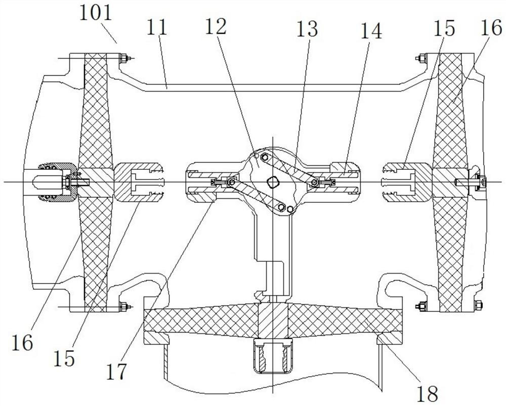
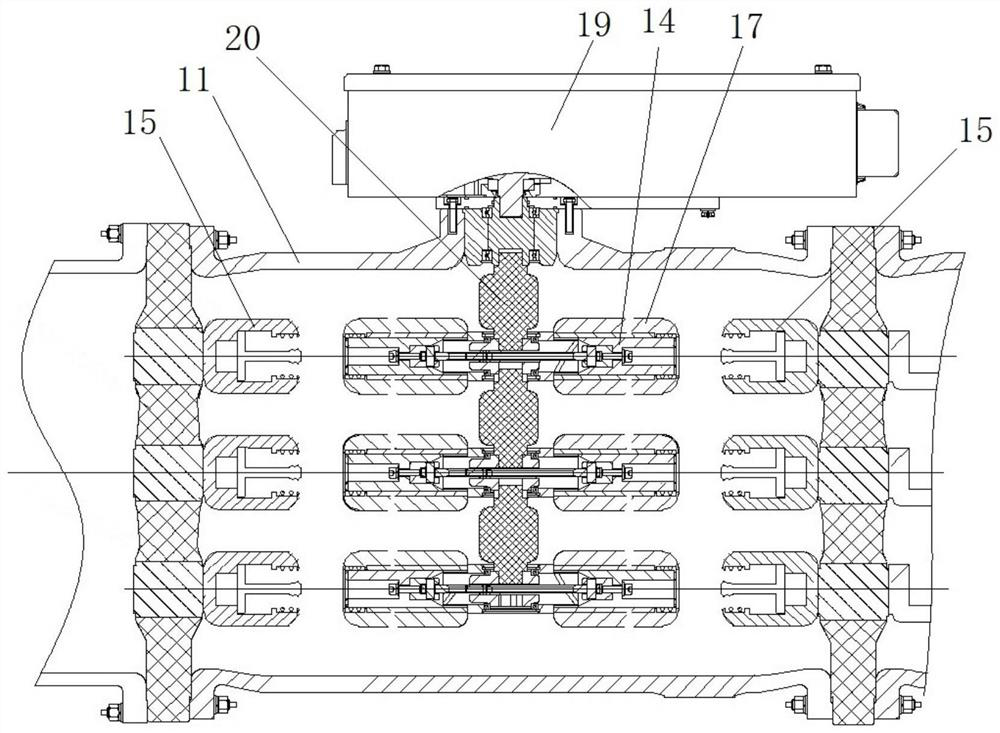
[0043] like figure 1 and figure 2 As shown, the double-break isolating switch 101 includes a cylinder body 11, with the axial direction of the cylinder body 11 as the left and right directions, the left and right ends of the cylinder body 11 are respectively provided with end insulators 16, and the inner sides of the two end insulators 16 are respectively fixed. There are static contacts 15 , two static contacts 15 are coaxially arranged, and the static contacts 15 are in the middle of the corresponding end insulators 16 . Wherein, the double-break isolating switch 101 is a three-phase common box structure. In other embodiments, the double-break isolating switch may be a single-phase box-divided structure.

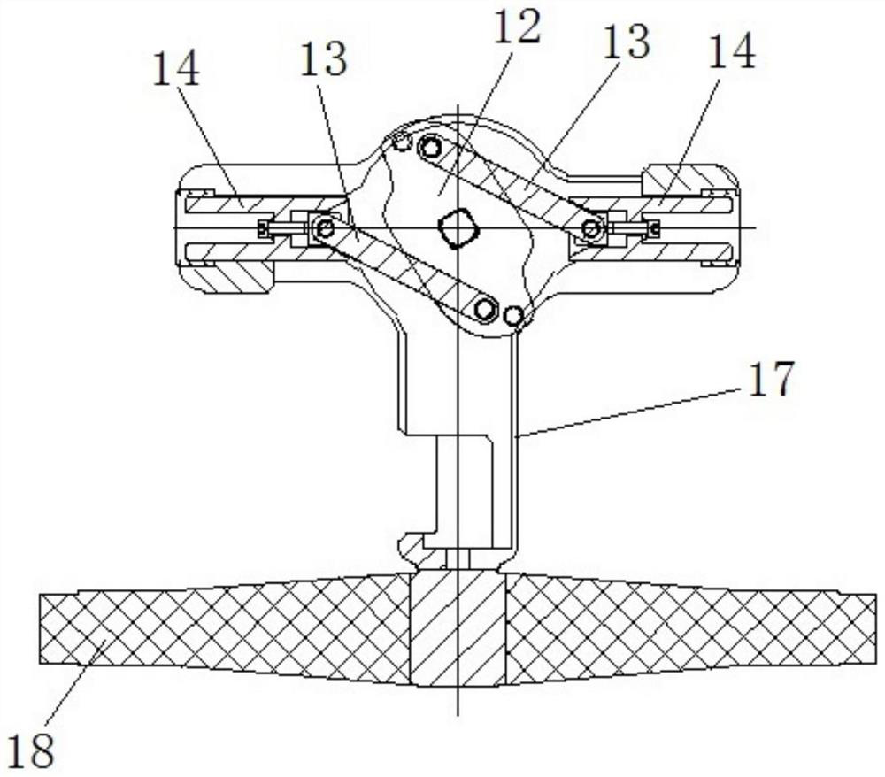
[0044] In this embodiment, a side insulator 18 is provided on the lower part of the cylinder body 11, and a movable contact seat 17 is fixed on the inner side of the side insulator 18. The movable contact seat 17 has a circular cavity and two guide holes, and the two gu...

Embodiment 2

[0059] The difference between this embodiment and Embodiment 1 is that in Embodiment 1, the rotating member is a rotating crank arm. In this embodiment, the rotating member is a rotating disk. In other embodiments, in order to avoid interference between the rotating disk and the movable contact, avoidance gaps may be provided at corresponding positions of the rotating disk.

Embodiment 3

[0061] The difference between this embodiment and embodiment 1 lies in that in embodiment 1, an avoidance notch for avoiding the corresponding moving contact is provided on the rotating crank arm. In this embodiment, when the moving stroke of the movable contact is relatively small, no escape gap may be provided.


PUM


Abstract

The invention relates to a double-fracture isolating switch, which comprises a cylinder body, end insulators are respectively arranged at two axial ends of the cylinder body, fixed contacts are respectively and fixedly arranged on the inner sides of the two end insulators, and the two fixed contacts are coaxially arranged; a side insulator is arranged at the side part of the cylinder body, a moving contact seat is fixedly arranged at the inner side of the side insulator, the moving contact seat is provided with two guide holes, the two guide holes are coaxially arranged, moving contacts are respectively assembled in the two guide holes in a guiding and sliding manner, and the moving contacts and the corresponding static contacts are coaxially arranged so as to be in conductive insertion connection with the corresponding static contacts; a rotating part is rotationally assembled on the moving contact seat, a connecting rod is arranged between the rotating part and the corresponding moving contact, one end of the connecting rod is hinged with the rotating part, and the other end of the connecting rod is hinged with the moving contact; the hinged positions of the two connecting rods and the rotating piece are symmetrically arranged with the rotating center of the rotating piece as the center. Compared with the staggered arrangement of the two moving contacts, the size of the double-break isolating switch can be reduced while the insulation is ensured, and the compact design is facilitated.

Description

technical field [0001] The invention relates to a GIS power station, in particular to a double-break isolating switch of the GIS power station. Background technique [0002] In order to reduce infrastructure and operation and maintenance costs, relatively large GIS power stations are generally constructed in stages, and most GIS power stations need to be expanded, while the first-phase equipment of GIS power stations only has expansion interfaces reserved, and bus power failure is required during expansion; at the same time, when a certain GIS power station When a fault occurs in a bay, the bay needs to be overhauled separately, and the bus power is also required to be cut off. [0003] At present, the main reason why the GIS power station cannot realize non-stop power expansion and maintenance is: since the isolating switch has only one isolation fracture, in order to avoid personal injury caused by sudden discharge breakdown of the isolation fracture, the original operatin...

Claims


Application Information

Patent Timeline
IPC IPC(8): H01H31/02H01H31/10
CPCH01H31/026H01H31/023H01H31/10H01H31/02
Inventor 占小猛焦淑敏魏建巍董祥渊柴影辉谭盛武段晓辉江经华杨敏贺永明高远谢世超温铭丽徐华靳幸福李斐井琼琼仓韬谭恺阳白杨鲁世浩庞建张振苏士伟
Owner PINGGAO GRP
Why Eureka
Try Eureka