Drainage system for condensate water of soil-air heat exchanger and using method of drainage system
An air heat exchanger and condensed water technology, which is applied in steam/steam condensers, household heating, geothermal collectors, etc. The effect of breeding and ensuring air quality
- Summary
- Abstract
- Description
- Claims
- Application Information
AI Technical Summary
Problems solved by technology
Method used
Image


Examples
Embodiment 1
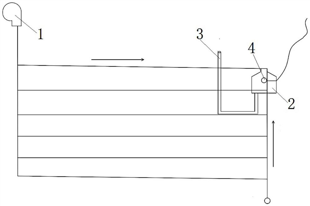
[0070] as attached figure 1 As shown, the present embodiment 1 provides a discharge system for condensed water in soil-air heat exchangers, and the discharge system is used for discharging condensed water in U-shaped multi-channel soil-air heat exchangers; the discharge The system includes fan 1, liquid collection tank 2, drain pipe 3 and ball float valve 4.
[0071] The fan 1 is arranged at the inlet end of the U-shaped multi-channel parallel soil-air heat exchanger, and is used to blow air into the pipeline of the U-shaped multi-channel parallel soil-air heat exchanger; the liquid collection tank 2 It is arranged in parallel on the terminal branch pipe far away from the inlet end of the U-shaped multi-path parallel soil-air heat exchanger.
[0072]The liquid collection tank 2 includes a liquid collection branch pipe and a liquid collection tank body; the liquid collection branch pipe is arranged in parallel with the terminal branch pipe; one end of the liquid collection bra...
Embodiment 2
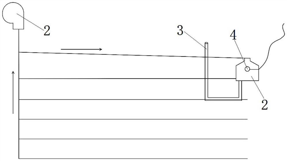
[0082] as attached figure 2 As shown, the structure and principle of this embodiment 2 are basically the same as that of embodiment 1, the difference is: in this embodiment 2, it is used to discharge the condensed water in the Z-type multi-channel soil-air heat exchanger; The tank 2 is arranged in parallel on the initial branch pipe near the inlet end of the Z-type multi-channel parallel soil-air heat exchanger; the liquid collection branch pipe in the liquid collection tank 2 is arranged in parallel with the initial branch pipe; one end of the liquid collection branch pipe It is connected to the inlet end of the starting branch pipe, and the other end is connected to the inlet end of the liquid collecting tank body; the liquid collecting tank body is located at the end position of the starting branch pipe; the inlet end of the liquid collecting tank body is also connected to the The Z-type multi-channel parallel soil-air heat exchanger is connected to the inlet end of the ou...
Embodiment 3
[0085] as attached image 3 As shown, the structure and principle of this embodiment 3 are basically the same as that of embodiment 2, the difference is that: in this embodiment 3, it is used to discharge the condensed water in the L-type multi-channel soil-air heat exchanger; The tank 2 is arranged in parallel on the initial branch pipe near the inlet end of the L-type multi-channel parallel soil-air heat exchanger; the liquid collection tank 2 includes a liquid collection branch pipe and a liquid collection tank body; the liquid collection branch pipe and the initial branch pipe Arranged in parallel; one end of the liquid collection branch pipe is connected to the inlet end of the initial branch pipe, and the other end is connected to the inlet end of the liquid collection tank body; the liquid collection tank body is located at the end of the initial branch pipe.
[0086] In Example 3, the heat exchange pipelines in the L-shaped multi-channel parallel soil-air heat exchange...
PUM
 Abstract
Description
Claims
Application Information
 - R&D
- Intellectual Property
- Life Sciences
- Materials
- Tech Scout
- Unparalleled Data Quality
- Higher Quality Content
- 60% Fewer Hallucinations
Browse by: Latest US Patents, China's latest patents, Technical Efficacy Thesaurus, Application Domain, Technology Topic, Popular Technical Reports.
© 2025 PatSnap. All rights reserved.Legal|Privacy policy|Modern Slavery Act Transparency Statement|Sitemap|About US| Contact US: help@patsnap.com