Shape-adjustable optical lens edge grinding device

An optical lens and edging technology, which is applied in the direction of grinding drive device, grinding automatic control device, grinding machine, etc., can solve the problems of lens edging and low practicability, so as to prevent grinding failure, reduce difficulty, and avoid position deviation moving effect

Inactive Publication Date: 2022-04-29
江西超联光电科技有限公司
View PDF1 Cites 0 Cited by
  • Summary
  • Abstract
  • Description
  • Claims
  • Application Information

AI Technical Summary

Problems solved by technology

[0005] Aiming at the deficiencies of the prior art, the present invention provides an adjustable shape optical lens edging device capable of edging lenses of different shapes, so as to overcome the inability of the existing devices to edging lenses of different shapes, so that the practicability lower disadvantage

Method used


Image

  • Shape-adjustable optical lens edge grinding device
  • Shape-adjustable optical lens edge grinding device
  • Shape-adjustable optical lens edge grinding device

Examples


Embodiment 1

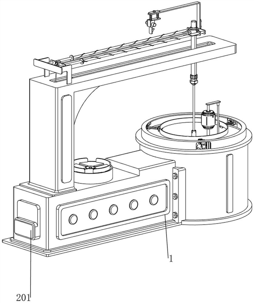
[0038] see Figure 1-Figure 5 , an optical lens edging device with adjustable shape, including a first connecting frame 1, a connecting frame 2, a rotating disk 3, a first connecting rod 4, a sliding rod 5, a grinder 501, a first spring 6 and a fixing mechanism 7. The connecting frame 2 is welded on the right side of the first connecting frame 1, and the upper part of the connecting frame 2 is rotatably connected to the rotating disk 3. The right side of the rotating disk 3 is provided with a first connecting rod 4, and the first connecting rod 4 is slidingly connected with a Sliding rod 5, two first springs 6 are connected between the lower right side of sliding rod 5 and the first connecting rod 4, a polisher 501 is provided on the upper side of sliding rod 5, and a fixing mechanism 7 is provided on the right side of the first connecting frame 1 .

[0039] see Figure 2-Figure 5 , the fixing mechanism 7 includes a connecting plate 71, a threaded sleeve 72, a clamping block 7...

Embodiment 2

[0042] On the basis of Example 1, please refer to figure 2 , Figure 6 and Figure 7 , also includes a discharge mechanism 8, the discharge mechanism 8 includes a second connection frame 81, a second connection rod 82, a clamping plate 83 and a second spring 84, the left side of the first connection frame 1 is welded with a second connection frame 81, the second connecting frame 81 top is welded with the second connecting rod 82, and the four sides of the second connecting rod 82 are slidably connected with clamping plates 83, and the lower sides of the four clamping plates 83 are connected with the second connecting rod 82 A second spring 84 is connected therebetween.

[0043] see figure 2 , Figure 8 and Figure 9 , also includes a pick-and-place mechanism 9, the pick-and-place mechanism 9 includes a fixed frame 91, a third connecting rod 92, a first electric push rod 93, a fourth spring 94, a photoelectric sensor 95, a first distance sensor 905, and a connecting pipe...


PUM


Abstract

The invention relates to an optical lens edge grinding device, in particular to a shape-adjustable optical lens edge grinding device. The shape-adjustable optical lens edge grinding device provided by the invention can be used for grinding the edges of lenses in different shapes. An optical lens edge grinding device with the adjustable shape comprises a first connecting frame, a connecting frame, a rotating disc, a first connecting rod, a sliding rod, a grinding device, a first spring and the like, the connecting frame is connected to the right side of the first connecting frame, the rotating disc is rotationally connected to the upper portion of the connecting frame, and the first connecting rod is arranged on the right side of the rotating disc; the sliding rod is slidably connected into the first connecting rod, the two first springs are connected between the lower right side of the sliding rod and the first connecting rod, and the polisher is arranged on the upper side of the sliding rod. According to the lens polishing device, the guide ring in the same shape as the lens is replaced, so that the guide ring guides the sliding rod, and therefore, the purpose of polishing the lenses in different shapes can be achieved.

Description

technical field [0001] The invention relates to an optical lens edging device, in particular to an optical lens edging device with adjustable shape. Background technique [0002] As a fashion item, glasses have more and more shapes of lenses, so when the lenses are processed, they will be processed into one or more curved surfaces to improve the fashion sense of the glasses, and the edges of the lenses need to be polished during lens processing. [0003] The patent publication number is CN211277754U, which discloses an optical lens edging device, which includes a base plate and a clamping mechanism. The top of the base plate is provided with a chute, and the inner cavity of the chute is provided with a clamping mechanism. The four corners of the vertical rod are fixedly connected with a vertical rod, the top of the vertical rod is fixedly connected with a top plate, and the right side of the bottom of the top plate is fixedly connected with an electric telescopic rod. The p...

Claims


Application Information

Patent Timeline
IPC IPC(8): B24B9/14B24B9/20B24B17/02B24B47/00B24B41/06B24B41/00B24B51/00B24B49/00
CPCB24B9/14B24B9/146B24B9/20B24B17/02B24B47/00B24B41/06B24B41/005B24B51/00B24B49/00
Inventor 刘金屏蔡福军
Owner 江西超联光电科技有限公司
Why Eureka
Try Eureka