
A cutting device for metal decorative strips

A technology for metal decorative strips and cutting devices, which is applied to metal sawing equipment, sawing machine devices, metal processing equipment, etc. It can solve the problems of cutting surface grinding and metal strips can not be realized, and achieve the effect of improving work efficiency and cutting quality

Active Publication Date: 2021-12-24
南通航远机械设备有限公司
View PDF12 Cites 0 Cited by
  • Summary
  • Abstract
  • Description
  • Claims
  • Application Information

AI Technical Summary

Problems solved by technology

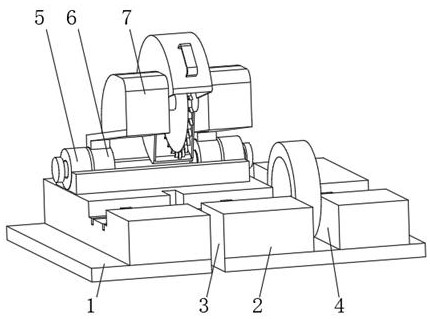
[0006] Aiming at the deficiencies of the prior art, the present invention provides a metal decorative strip cutting device, which solves the problem that the cutting surface of the metal strip after cutting cannot be polished by the device when cutting the metal strip. The burrs generated at the cutting edge are polished smoothly, which greatly improves the cutting quality of the metal decorative strip. It is convenient for the device to continue cutting the metal strip while grinding the incision, so that the grinding and cutting can be carried out at the same time, and it can work in a cycle, which improves the work efficiency. The dust accumulated on the surface of the metal strip is blown off, and the purpose of cleaning the air outlet and the filter screen is realized, which ensures the cleaning efficiency and improves the practicability of the device

Method used


Image

  • A cutting device for metal decorative strips
  • A cutting device for metal decorative strips
  • A cutting device for metal decorative strips

Examples


Embodiment 1

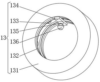
[0029] see Figure 1-5 , the present invention provides a technical solution: a metal decorative strip cutting device, including a base plate 1, a cutting table 2 is fixedly connected to the top of the base plate 1, a cutting opening 3 is opened on one side of the cutting table 2, and a cutting port 3 is opened on the top of the cutting table 2 There is a device groove 4, the top of the cutting table 2 is connected with a rotating block 6 through the rotating seat 5, the rotating block 6 is provided with two groups, the top of the rotating block 6 is fixedly connected with a fixed plate 7, and the fixed plate 7 is fixedly connected. Dust cover 8, the outer side of dust cover 8 is fixedly connected with handle 9, and the inner wall of dust cover 8 is installed with drive motor 10, and the output end of drive motor 10 is connected with rotating rod 11 in rotation, and the outer cover of rotating rod 11 is provided with cutting Knife 12, one end of rotating rod 11 away from drive...

Embodiment 2

[0038] see Figure 1-6 , the present invention provides a technical solution: on the basis of Embodiment 1, the clamping device 16 includes a sliding block 161, the sliding block 161 is provided with two groups, and the two groups of sliding blocks 161 are connected by a moving column, the sliding block 161 and The slide block inside the electronic rail 15 is fixedly connected, the top of the slide block 161 is equipped with a rubber splint 162, the bottom of the slide block 161 is fixedly connected with a magnet block 163 by extruding springs, the bottom of the magnet block 163 is equipped with a cleaning plate 164, and the magnet block 163 is rotatably connected with a scraper 165 near the side of the cleaning plate 164 .

[0039] When in use, the electronic guide rail 15 drives the clamping device 16 to move the metal strip to the cutting opening 3. At this time, the magnet block 163 moves along the electronic guide rail 15 along with the slider inside the electronic guide ...


PUM


Abstract

The invention discloses a metal decorative strip cutting device, which comprises a bottom plate, a cutting table is fixedly connected to the top of the bottom plate, a cutting opening is opened on one side of the cutting table, and a device groove is opened on the top of the cutting table. The top of the cutting table is rotatably connected with a rotatable block through a rotatable seat, and the rotatable block is provided with two groups, and the top of the rotatable block is fixedly connected with a fixed plate, and a dust cover is fixedly connected between the fixed plates. The outer side of the dust-proof cover is fixedly connected with a handle, the inner wall of the dust-proof cover is installed with a drive motor, the output end of the drive motor is rotatably connected with a rotating rod, and a cutting knife is set on the outer side of the rotating rod. The present invention relates to The field of metal processing technology. The metal decorative strip cutting device achieves the purpose of grinding the cut surface of the metal strip after cutting, smooths the burrs generated at the incision of the metal strip during cutting, and greatly improves the cutting quality of the metal decorative strip.

Description

technical field [0001] The invention relates to the technical field of metal processing, in particular to a metal decorative strip cutting device. Background technique [0002] With the rapid development of real estate, interior decoration has also attracted people's attention, especially for home decoration, people's requirements for home decoration are getting higher and higher. Metal decorative strips with good effect, but because the material of the metal decorative strips is relatively hard, they must be cut and combined into the required patterns to achieve the decorative effect. [0003] For example, Chinese patent CN111015333B proposes a cutting device for metal decorative strips, including a frame and a workbench mounted on the frame, a cutting unit, and a placement unit and a push-out unit positioned on the workbench. The placement unit includes a protective cover and a protective cover. The inner shelf has an opening at the bottom of the protective cover, the she...

Claims


Application Information

Patent Timeline
Patent Type & Authority Patents(China)
IPC IPC(8): B23P23/04B23D47/04B23D47/12B23Q11/00B08B15/02B24B9/04B24B55/06
CPCB23P23/04B23D47/04B23D47/12B23Q11/0042B08B15/02B24B9/04B24B55/06
Inventor 章坚毛雷徐新建
Owner 南通航远机械设备有限公司
Learn More