
Robotic cutting method for profile steel

A cutting method and robot technology, applied in the direction of instruments, special data processing applications, electrical digital data processing, etc., can solve the problems of poor cutting quality, complex modeling of section steel cutting features, manual secondary processing, etc.

Active Publication Date: 2011-09-21
HARBIN INST OF TECH
View PDF4 Cites 23 Cited by
  • Summary
  • Abstract
  • Description
  • Claims
  • Application Information

AI Technical Summary

Problems solved by technology

[0004] At present, most of the off-line programming technologies of robots used for steel cutting have the following disadvantages: 1) The modeling of steel cutting features is complicated and unsuitable for workers to operate; 2) The cutting groove angle can only be set to a fixed groove on one side of the steel surface 3) In the cutting of angle steel, spherical flat steel, etc., the cutting quality at the corner where the two profiles intersect is poor, and manual secondary processing is required.

Method used


Image

  • Robotic cutting method for profile steel
  • Robotic cutting method for profile steel
  • Robotic cutting method for profile steel

Examples


Embodiment Construction

[0018] The technical solutions in the embodiments of the present invention will be clearly and completely described below with reference to the accompanying drawings in the embodiments of the present invention. Obviously, the described embodiments are only a part of the embodiments of the present invention, but not all of the embodiments. Based on the embodiments of the present invention, all other embodiments obtained by those of ordinary skill in the art without creative efforts shall fall within the protection scope of the present invention.

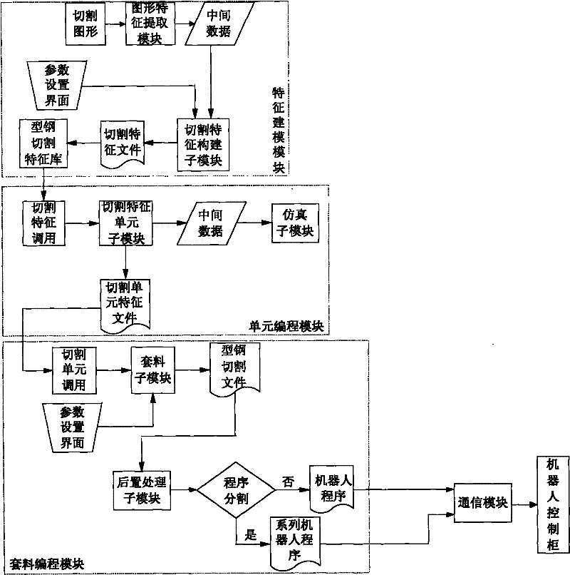
[0019] A robot cutting system for shaped steel according to an embodiment of the present invention includes: a feature modeling module, a unit programming module and a nesting programming module, wherein:

[0020] The feature modeling module realizes the conversion from graphic files (DXF files generated by CAD and GEN files generated by TRIBON) to profile steel cutting features, extracts graphic feature requirements for profile steel ...


PUM


Abstract

The invention discloses a robotic cutting method for profile steel, which is based on the robot offline programming. The method comprises the following steps of: reading a CAD graphics file to obtain geometrical characteristics of profile steel cutting; generating a cutting unit by a path planning and a cutting parameter design of the geometrical characteristics; determining an action parameter and a cutting parameter of a cutting gun and generating a trepanning file by a placement planning of the cutting unit on profile steel having a specific length; converting the trepanning file to be a robot executable program in accordance with the robot program format, and achieving the cutting of the profile steel. Based on the robot offline programming technology, by utilizing the designed information of CAD graphics directly, the robotic cutting precision and efficiency can be increased; the method is suitable for cutting requirements of groove-type profile steels, such as V-type, Y-type andthe like and varied-groove-type profile steel; the problem of the poor cutting quality at the edge of an angle steel or other steels is solved; the method has the characteristics of generality, flexibility, high efficiency and high precision.

Description

technical field [0001] The invention relates to the field of shipbuilding, in particular to a robot cutting method for section steel. Background technique [0002] The shipbuilding industry has a huge amount of material cutting and high quality requirements. Before welding, marine section steel needs to be cut into various shapes of ends, intermediate holes and welding grooves. The traditional manual scribe cutting or special machine scribe cutting has low cutting efficiency and poor quality, which seriously restricts the development of the shipbuilding industry. This greatly increases the requirements for automated production of marine section steel cutting, and the use of robotic flexible cutting technology can well meet the needs of cutting production. However, if the teaching method is used, the required man-hours are long, the cutting efficiency is low, and the cutting accuracy is greatly reduced, which affects the overall performance of the system. The use of CAD / CAM / ...

Claims


Application Information

Patent Timeline
IPC IPC(8): B23K31/10G06F17/50
Inventor 李海超巩杉高洪明张广军
Owner HARBIN INST OF TECH
Learn More